Acoustic damping system for a combustor of a gas turbine engine

a technology of acoustic damping system and gas turbine engine, which is applied in the direction of machines/engines, burner noise abatement, light and heating equipment, etc., can solve the problems of high repair cost and restrict the tuning flexibility of gas turbine engines, and achieve the effect of improving the mixing profile and increasing the operating envelope of the turbine engin

Active Publication Date: 2017-09-28
SIEMENS ENERGY GLOBAL GMBH & CO KG
View PDF15 Cites 7 Cited by
  • Summary
  • Abstract
  • Description
  • Claims
  • Application Information

AI Technical Summary

Benefits of technology

[0010]During use, the acoustic damping resonator system may dampen the longitudinal mode combustion dynamics, thereby permitting the turbine engine operating envelope to be increased. The acoustic damping system may function as a flow conditioner by creating a more uniform flow at the combustor inlet and by creating better mixing profile downstream.

Problems solved by technology

The dynamics restrict the tuning flexibility of the gas turbine engine in order to operate at lower emissions, which is an ever increasing requirement for newer gas turbines.
Early configurations including welding resonators directly to the combustor, but often failed due to formation of cracks caused by residual stress and thermal gradients between the weld and the liner, leading to high repair costs, other solutions have been used with limited success because of cracking and significant repair costs.

Method used


Image

  • Acoustic damping system for a combustor of a gas turbine engine
  • Acoustic damping system for a combustor of a gas turbine engine
  • Acoustic damping system for a combustor of a gas turbine engine

Examples


Embodiment Construction

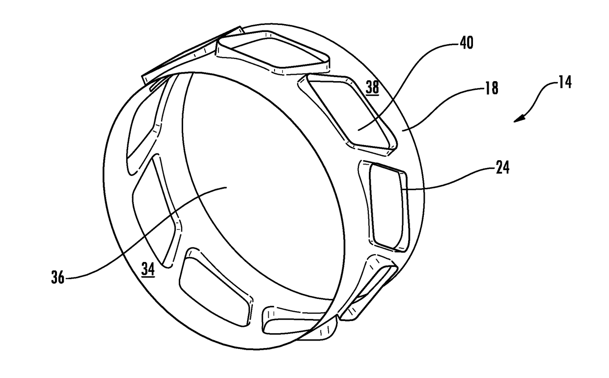
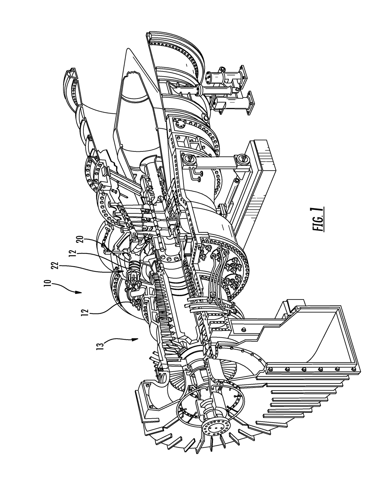
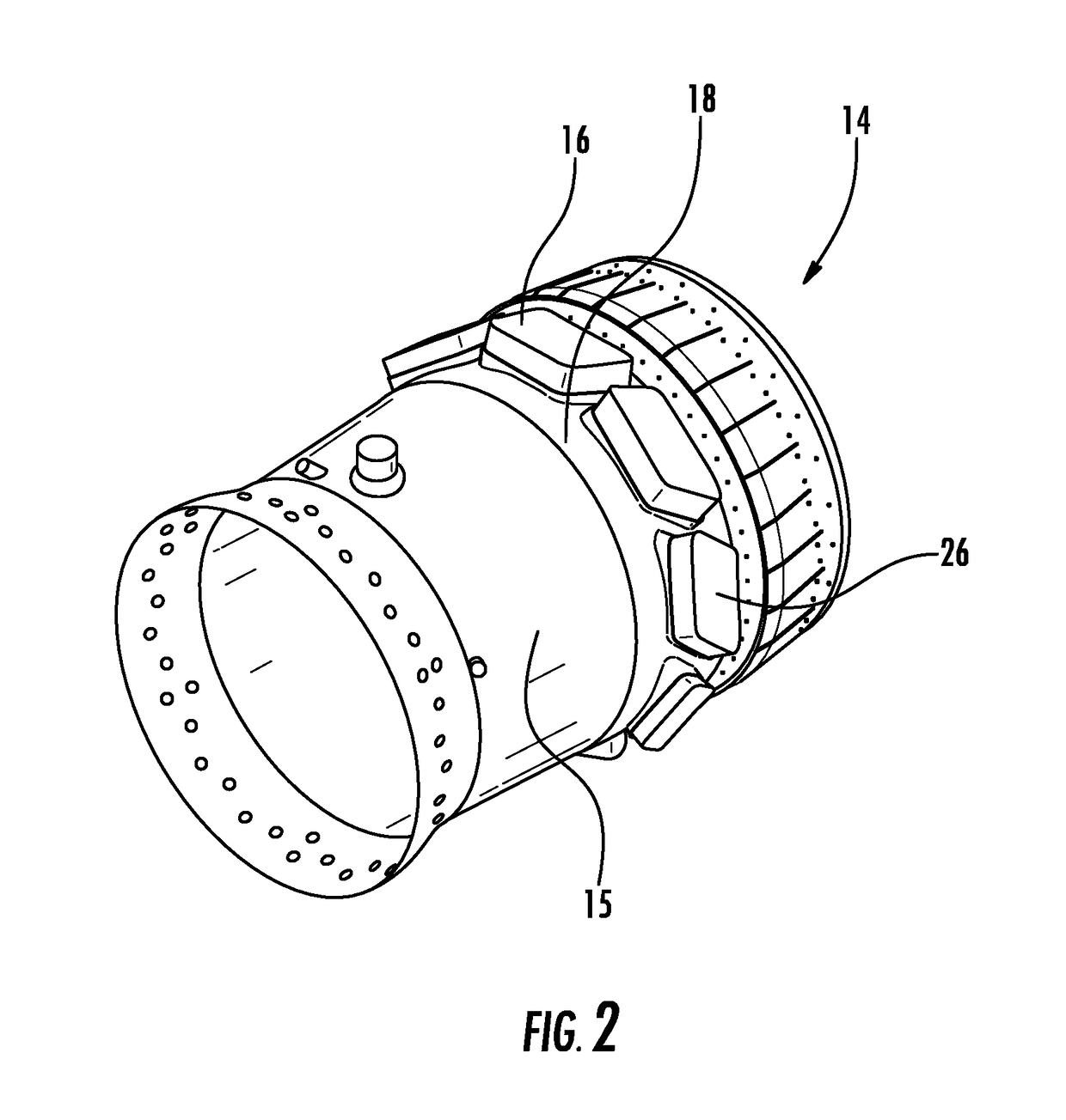
[0022]As shown in FIGS. 1-9, an acoustically dampened gas turbine engine 10 having a gas turbine engine combustor 12 with an acoustic damping resonator system 14 is disclosed. The acoustic damping resonator system 14 may be formed from one or more resonators 16 formed from a resonator housing 18 positioned within the gas turbine engine combustor 12 at an outer housing 20 forming a combustor basket 22 and extending circumferentially within the combustor 12. In at least one embodiment, the resonator housing 18 may include one or more resonator chamber receivers 24 supporting one or more resonator chambers 26, whereby the resonator chambers 26 may be welded in place within the resonator chamber receivers 24 but easily replaceable without exposing the resonator housing 18 to damage. In another embodiment, a joint 28 formed between the resonator chamber 26 and the resonator housing 18 may form a crevice 30 whereby an inner surface 32 of the resonator chamber 26 is offset radially outward...


PUM


Abstract

An acoustically dampened gas turbine engine (10) having a gas turbine engine combustor (12) with an acoustic damping resonator system (14) is disclosed. The acoustic damping resonator system (14) may be formed from one or more resonators (16) formed from a resonator housing (18) positioned within the gas turbine engine combustor (12) at an outer housing (20) forming a combustor basket (22) and extending circumferentially within the combustor (12). In at least one embodiment, the resonator housing (18) may include resonator chambers (26) that may be welded in place within resonator chamber (26) receivers (24) but easily replaceable without exposing the resonator housing (18) to damage. In another embodiment, an inner surface (32) of the resonator chamber (26) may be offset radially outward from an inner surface (34) of the resonator housing (18), thereby creating a flow-path discontinuity and reducing heating of the resonator chamber (26). The acoustic damping resonator system (14) may mitigate dynamics thereby increasing an engine operating envelope and decreasing emissions.

Description

FIELD OF THE INVENTION[0001]The present invention relates in general to gas turbine engines and, more particularly, to acoustic damping systems for damping dynamics in combustors in gas turbine engines.BACKGROUND OF THE INVENTION[0002]Gas turbine engines typically include a plurality of combustor baskets positioned downstream from a compressor and upstream from a turbine assembly. During operation, longitudinal mode dynamics often occurs in the combustor baskets. The longitudinal mode dynamics usually originates at the inlet of the air flow path in a combustor basket and travels downstream to the turbine inlet. The dynamics restrict the tuning flexibility of the gas turbine engine in order to operate at lower emissions, which is an ever increasing requirement for newer gas turbines.[0003]Resonators have been incorporated into combustors to damp the longitudinal mode dynamics. The resonators have been sized and configured to address specific acoustic tunes. Resonators with various co...

Claims


Application Information

Patent Timeline
Patent Type & Authority Applications(United States)
IPC IPC(8): F23M20/00F23R3/06F23R3/00F02C7/24
CPCF23M20/005F02C7/24F23R3/06F23D2210/00F23R3/04F05D2260/96F23R2900/00014F23R3/002
Inventor SCHILP, REINHARDRITLAND, DAVID M.DEANE, ERICK J.SHARMA, JAISHREEMARKOVITZ, JOSEPH SCOTT
Owner SIEMENS ENERGY GLOBAL GMBH & CO KG
Why Eureka
Try Eureka