High power flywheel system

a flywheel and high-power technology, applied in the direction of magnetic circuits characterised by magnetic materials, magnetic circuit shapes/forms/construction, magnetic circuit rotating parts, etc., can solve the problems of reducing efficiency, affecting the efficiency of flywheels, and prohibiting the application of conventional energy storage solutions, so as to achieve high efficiency, reduce the effect of on-rotor losses and high cycle li

Active Publication Date: 2017-09-28
HELIX POWER
View PDF3 Cites 14 Cited by
  • Summary
  • Abstract
  • Description
  • Claims
  • Application Information

AI Technical Summary

Benefits of technology

[0012]An object of the invention is to provide a flywheel system using a rotor with very high cycle life and a built in motor-generator that operates at very high efficiency with negligible on-rotor losses.
[0013]A further object of the invention is to provide able to provide flywheel system capable of MW charge and discharge through many cycles, respond rapidly, and be compact and deployable in many applications.

Problems solved by technology

Areas of the grid experience surges, sags and ramps when variable renewable energy sources, particularly wind and solar, provide a significant fraction of the generated power.
Heretofore, the high power and high number of cycles of these disturbances has made it prohibitive for conventional energy storage solutions to be applied.
Instead, the excessive fluctuations are dealt with by ramping generating assets with the consequence of reduced efficiency, higher energy cost, higher O&M cost, and reduced service life.
No battery or capacitor can economically provide this capability without periodic replacement or significant oversizing.
Pumped hydro storage cannot respond as rapidly and is neither compact nor transportable.
Heretofore no flywheel energy storage system has attained all of these capabilities including power and stored energy.
Consequently batteries are useful in applications with limited cycle life such as vehicles but cannot withstand long-term operation with frequent cycling.
Ultra-capacitors have much greater cycle life than batteries but degrade after several hundred thousand cycles and are costly when sized to store more than a few seconds worth of energy.
However, operation with continuous high power cycling has proven challenging.
Even small inefficiencies resulting in losses on the rotor can cause excessive rotor heating.

Method used


Image

  • High power flywheel system
  • High power flywheel system
  • High power flywheel system

Examples


Embodiment Construction

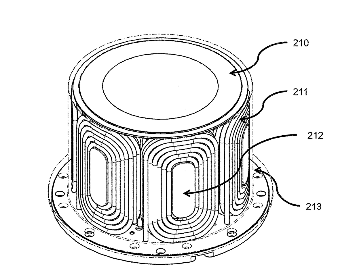
[0021]A flywheel system stores and retrieves electrical energy. The system may communicate with AC or DC systems. In the case of an AC application, the flywheel system comprises an inverter that transfers energy between the application and a DC bus and a motor drive that transfers energy between the DC bus and the motor within the flywheel module itself. For DC applications, a motor drive transfers energy between the DC application and the motor within the flywheel module. The flywheel module comprises the flywheel rotating assembly, the stator, bearings, the housing and various other elements, such as sensors. In addition to the inverter, motor drive, and flywheel module, ancillary systems such as the vacuum pump and cooling system make up the balance of the system. During charging, energy is drawn from the application and used to accelerate the rotor thereby converting electrical energy into kinetic energy. During discharging, the motor is operated as a generator decelerating the ...


PUM


Abstract

A flywheel energy storage system includes a rotating assembly having a plurality of magnets and a longitudinal axis about which the rotating assembly rotates and static assembly having a stator configured to magnetically interact with the plurality of magnets of the rotating assembly. The rotating assembly includes a rotor back iron supporting the plurality of magnets and disposed further from the longitudinal axis in a radial direction than the plurality of magnets. The back iron being formed of a material having a first stiffness, relative permeability of at least 10, and an electrical conductivity 10% or less than the electrical conductivity of magnetic steel. There is composite structure supporting the rotor back iron and disposed further from the longitudinal axis in a radial direction than the rotor back iron. The composite structure comprises a composite material having a second stiffness, which is greater than the first stiffness.

Description

CROSS REFERENCE TO RELATED APPLICATION[0001]This application claims the benefit of the priority date of U.S. Provisional Application No. 62 / 042,021, filed on Aug. 26, 2014, the contents of which are incorporated herein by reference in their entirety.FIELD OF INVENTION[0002]This invention relates to high power flywheel systems and more particularly to such a flywheel system with the ability to cycle continuously at more than approximately 200 kW.BACKGROUND[0003]Short duration power variations on a MW scale occur in many different systems. For example, electrified rail experiences voltage surges and sags when trains decelerate and accelerate. Areas of the grid experience surges, sags and ramps when variable renewable energy sources, particularly wind and solar, provide a significant fraction of the generated power. Draglines used at mines, material handling equipment, and islanded systems all experience frequent, short duration MW scale power fluctuations. Heretofore, the high power a...

Claims


Application Information

Patent Timeline
Patent Type & Authority Applications(United States)
IPC IPC(8): H02K7/02H02K1/30
CPCH02K7/025H02K1/30H01F3/08H02K1/27H02K7/02H02K2213/03Y02E60/16H02K1/02H02K1/2791
Inventor BENDER, DONALDLAZAREWICZ, MATTHEW
Owner HELIX POWER
Why Eureka
Try Eureka