Automatic analyzer and method

a technology of automatic analysis and analyzer, applied in the direction of material analysis, instruments, etc., can solve the problems of labor-intensive routine performance of these measures, significant change in the fluid volume delivered with given pump parameters within relatively short periods of time, and aging of the pump used, etc., to achieve a stable dilution ratio

Active Publication Date: 2017-10-05
ENDRESSHAUSER CONDUCTA GMBHCO
View PDF0 Cites 9 Cited by
  • Summary
  • Abstract
  • Description
  • Claims
  • Application Information

AI Technical Summary

Benefits of technology

[0009]It is, therefore, the aim of the present disclosure to specify an improved generic analyzer and a method for operating the analyzer. In particular, the analyzer is to be designed such that a stable dilution ratio can be set for the long term, without frequent maintenance measures being required.

Problems solved by technology

However, this setting of the dilution ratio, i.e., the dosing of the sample fluid and of a dilution medium to be mixed with the sample fluid, by controlling two separate pumps has disadvantages: The transport of the fluids in automatic analyzers takes place via fluid lines, the respective internal volume of which can change over the service life of the devices for example, by gradual clogging of the fluid lines with a polluting load present in the sample fluid or by other formation of deposits or vegetation inside the fluid lines.
The pumps used can also be exposed to aging and material fatigue, so that the fluid volume transported using a pump with given operating parameters and given transport time also called the feed rate changes over the service life of the pump.
As a result of the mechanical loading of the hose lines, a significant change in the fluid volume delivered with given pump parameters occurs within relatively short periods of time.
The routine performance of these measures is, however, labor-intensive and causes routine interruptions of the operation of the analyzer.

Method used


Image

  • Automatic analyzer and method
  • Automatic analyzer and method

Examples


Embodiment Construction

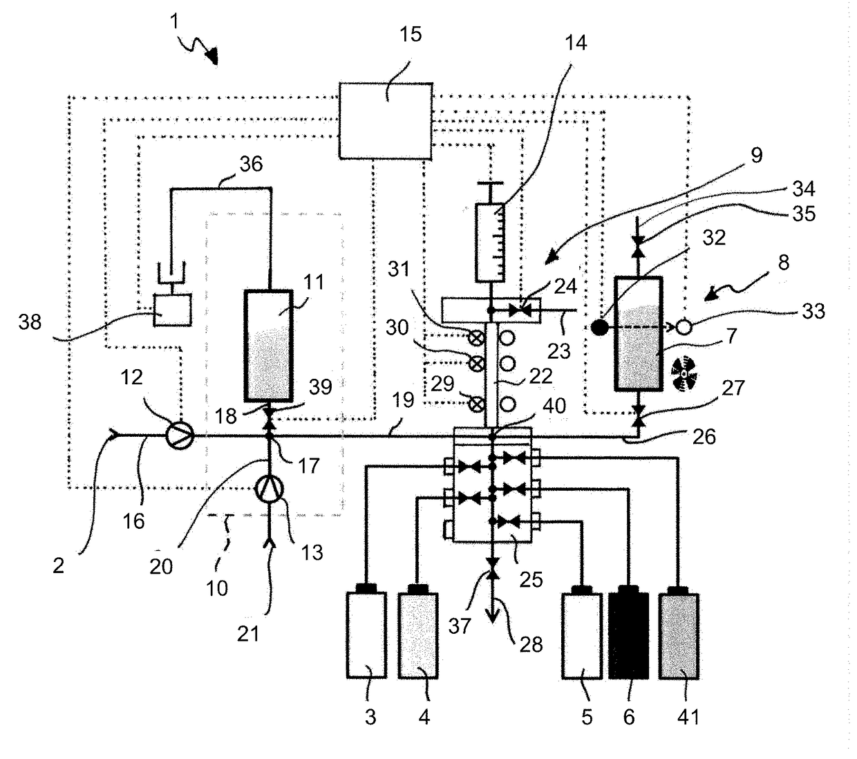
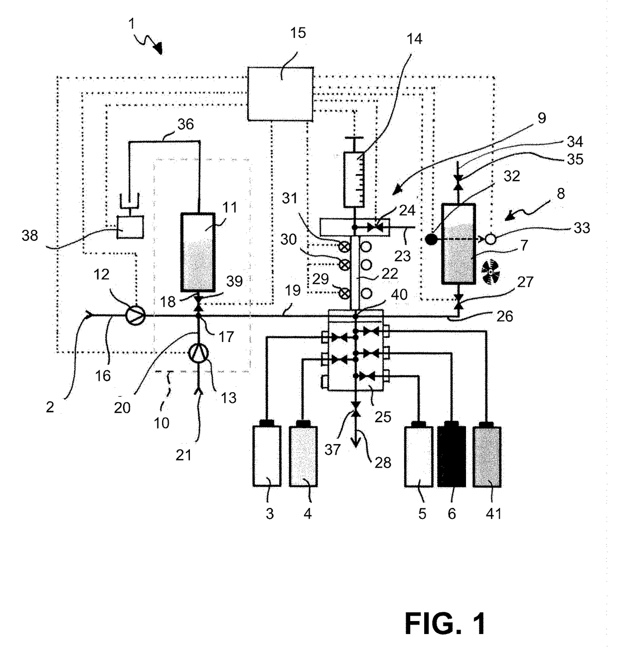
[0036]The analyzer 1 shown schematically in FIG. 1 is used to determine a parameter dependent upon at least one concentration of an analyte in a sample liquid serving as sample fluid. The analyzer 1 can, for example, be designed as a cabinet device, in which all components shown in FIG. 1 are combined in a cabinet (not shown). The parameter can, for example, be a sum parameter, such as chemical oxygen demand (COD) or total phosphorus (TP). The parameter can also be the concentration of a single substance, e.g., of a single ion type, such as sodium, ammonium, nitrate, or chloride. The sample fluid to be monitored by means of the analyzer 1 is provided in a sample receiving vessel 2. The sample fluid can, in particular, be a liquid, a liquid mixture, a multiphase mixture, e.g., a suspension or an emulsion in particular, a liquid with a solid load. The sample receiving vessel 2 can, for example, be a tank connected to a sampling point of a process to be monitored, into which tank the s...


PUM

PropertyMeasurementUnit
diameteraaaaaaaaaa
volumeaaaaaaaaaa
chemical oxygen demandaaaaaaaaaa

Abstract

The present disclosure relates to an automatic analyzer for determining a parameter of a sample fluid, including a dosing device comprising at least one dosing chamber, a first fluid flow path connecting a sample receiving vessel to the dosing chamber via a first pump, a tank containing a dilution medium, a second fluid flow path connecting the tank to the dosing chamber via a second pump, a measuring cell in communication with the dosing chamber via a third fluid flow path via a third pump, and a measuring and control system connected to and configured to control the pumps, wherein the first, second, and third fluid flow paths can selectively be blocked or unblocked by at least one valve unit and the measuring and control system is configured to control the at least one valve unit to block or unblock the first, second, and third flow paths.

Description

CROSS-REFERENCE TO RELATED APPLICATION[0001]The present application is related to and claims the priority benefit of German Patent Application No. 10 2016 105 770.3, filed on Mar. 30, 2016, the entire contents of which are incorporated herein by reference.TECHNICAL FIELD[0002]The present disclosure relates to an automatic analyzer for determining a parameter of a sample fluid, in particular a liquid sample, and a method for operating an analyzer.BACKGROUND[0003]In process measuring technology, e.g., in chemical, biotechnological, pharmaceutical, and food technology processes, as well as in environmental metrology, automatic analyzers are used to determine a measurand in a liquid sample. Analyzers may, for example, be used for the monitoring and optimization of the cleaning performance of a sewage treatment plant, monitoring drinking water, or monitoring quality of foods. Measured and monitored is, for example, the proportion of a certain substance, which is also called an analyte, i...

Claims


Application Information

Patent Timeline
Patent Type & Authority Applications(United States)
IPC IPC(8): G01N35/10G01N35/00
CPCG01N35/1002G01N2035/1025G01N35/00623G01N35/1065G01N35/00G01N35/1016G01N2035/00227G01N2035/00306G01N2035/00465
Inventor MUZ, ULRIKEABEL, ANNIKHOMA, JUSTYNASCHIPOLOWSKI, THOMAS
Owner ENDRESSHAUSER CONDUCTA GMBHCO
Why Eureka
Try Eureka