Coreless rotating electrical machine with stator including cylindrical coil and cooling method therefor

a technology of rotating electrical machines and cylindrical coils, which is applied in the direction of rotating parts of magnetic circuits, magnetic circuit shapes/forms/construction, windings, etc., can solve the problems of inability to thoroughly cool the coil formed by winding a lead wire for multiple turns, inability to fully cool, and inability to achieve the effect of improving the cooling

Active Publication Date: 2017-10-05
CORELESS MOTOR CO LTD
View PDF7 Cites 23 Cited by
  • Summary
  • Abstract
  • Description
  • Claims
  • Application Information

AI Technical Summary

Benefits of technology

[0130]The cup-type mount 400 may further be provided with a multi-vane centrifugal blowing rotating body 2000 fit into an outer cylindrical air-channel forming body 600 and configured like a water-turbine with two circular plates 2100 having a width corresponding to the third air space 30 and

Problems solved by technology

It is also well-known that copper loss or hysteresis which converts magnetic energy to thermal energy is an inevitable technical problem.
To address influence to output and/or efficiency of an electric motor induced by the above technical problem and heat-induced deterioration of coercive force of permanent magnets equipped on an outer surface of an inner yoke and/or on an inner surface of an outer yoke which configure a rotor, it has been attempted to cool coiled surface of windings, but it does not yet lead to fundamental solution.
The fixed armature is configured with a stator yoke in which a plurality of rectangular air-core coil, formed by winding a lead wire for

Method used


Image

  • Coreless rotating electrical machine with stator including cylindrical coil and cooling method therefor
  • Coreless rotating electrical machine with stator including cylindrical coil and cooling method therefor
  • Coreless rotating electrical machine with stator including cylindrical coil and cooling method therefor

Examples


Embodiment Construction

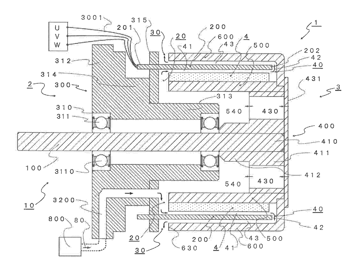
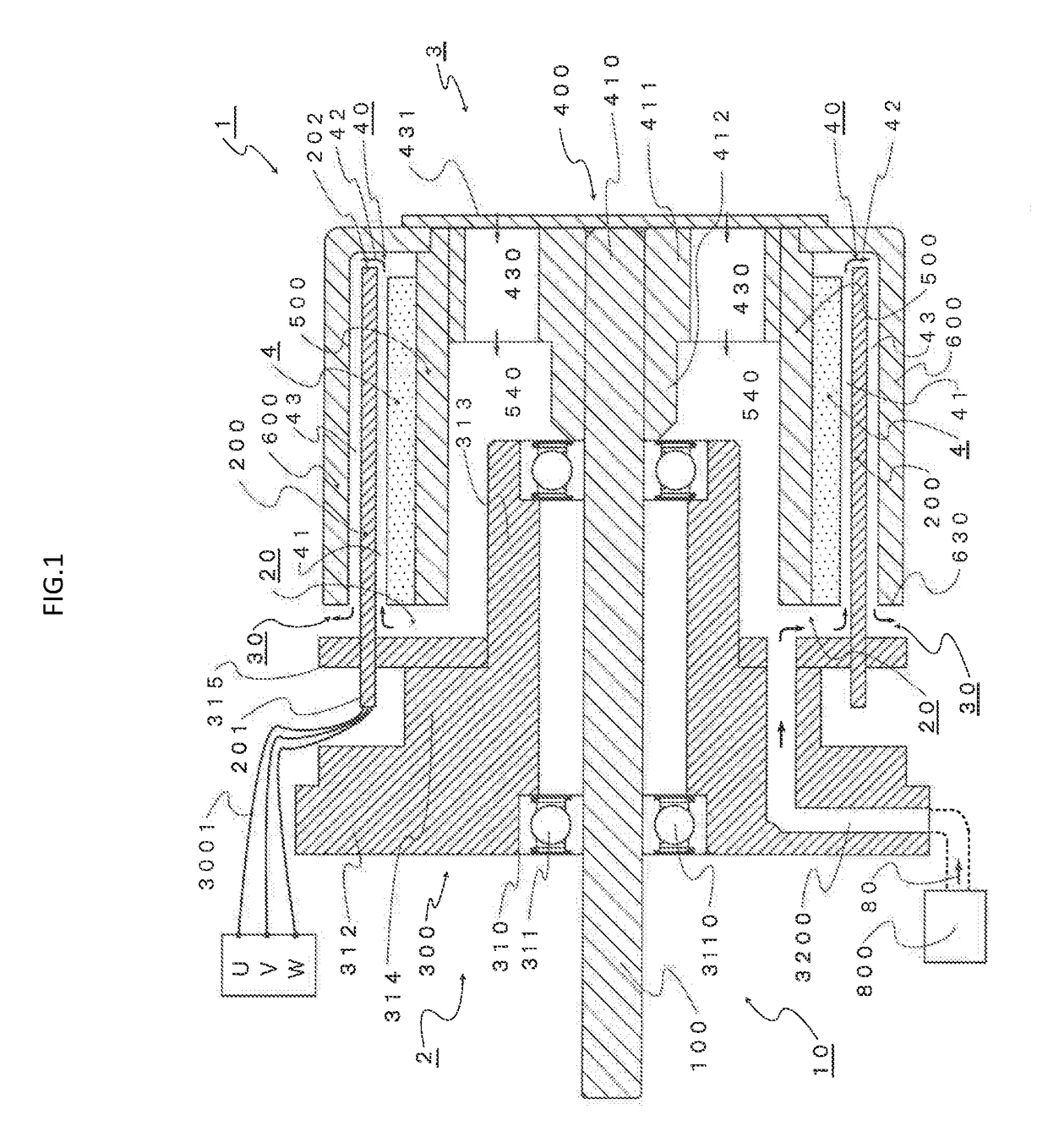
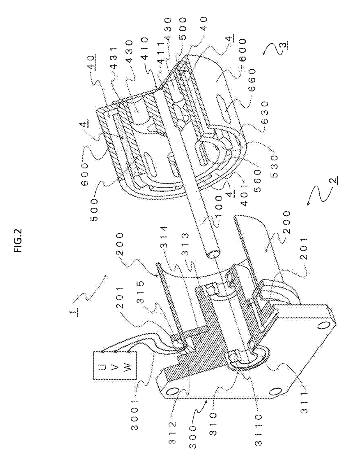
[0170]Generated torque T (N·m), one of performance indications of a rotating electrical machine, is proportional to current intensity I (A) flowing in an armature coil and an output P (W) is calculated as a product of the torque T (N·m) and a rotation angular speed ω (rad / s). On the other hand, for voltage drop, a power source voltage (V) equals to a sum of a product of the current I (A) flowing in the armature coil and a resistance R (Ω) of the armature coil, and a counter electromotive force E0 (V) which is induced electromotive force.

T=Kt×I  (1)

P=T×ω  (2)

V=IR+E0  (3)

[0171]From the above equations, it is found as important to reduce the coil resistance in order to increase torque and output.

[0172]In this regard, a coreless rotating electrical machine comprising a stator including a cylindrical coil which characterizes the present invention as shown in FIG. 1 to FIG. 15 (hereinafter referred as “an electric motor of the present invention”) is overviewed. A first feature of a basic ...


PUM


Abstract

A high performance rotating electrical machine which aims at downsizing, and challenges inevitable technical problems such as deterioration of efficiency η caused by copper loss and temperature rise inside the rotating electrical machine due to heat generation induced by eddy current generated in magnetic body.

Description

TECHNICAL FIELD[0001]The present invention relates to a coreless rotating electrical machine comprising a stator including a cylindrical coil and its cooling method. More specifically, the present invention relates to coreless rotating electrical machine constructed with a stator including a cylindrical coil which is cylindrically formed as a laminate structure of conductive metal sheets and a rotor sandwiching the cylindrical coil and forming air gap, and cooling method for cooling the air gap including the cylindrical coil of the coreless rotating electrical machineBACKGROUND ART[0002]An electric motor is a device which converts electrical energy to kinetic energy. An electric motor may be classified as DC motor or AC motor, inner-rotor type or outer-rotor type based on positional relationship of a stator and a rotor, and winding-field type or permanent-magnet type. Either classification includes an electric motor which utilizes so-called revolving-field, in which a stator revolve...

Claims


Application Information

Patent Timeline
IPC IPC(8): H02K3/47H02K5/16H02K1/27H02K9/06
CPCH02K3/47H02K1/274H02K5/161H02K9/06H02K21/14H02K1/278H02K5/15H02K5/1735H02K9/02H02K9/04H02K2213/03H02K3/24H02K7/083H02K7/14H02K9/08H02K16/02H02K2205/09H02K2203/06H02K2201/03
Inventor SHIRAKI, MANABUSHIRAKI, TSUTOMU
Owner CORELESS MOTOR CO LTD
Why Eureka
Try Eureka