Linear motor

a linear motor and micro-motor technology, applied in the direction of dynamo-electric machines, electrical equipment, supports/enclosements/casings, etc., can solve the problems of motor vibration failure, loss of vibration function, and affecting the stability of linear motors, so as to improve vibration stability and avoid noise generation. , the effect of improving the stability

Active Publication Date: 2017-10-05
JINLONG MACHINERY & ELECTRONICS CO LTD
View PDF4 Cites 11 Cited by
  • Summary
  • Abstract
  • Description
  • Claims
  • Application Information

AI Technical Summary

Benefits of technology

[0005]Therefore, one objective of the present invention is to overcome the deficiency that the magnet within the suspension components of linear motors in prior art tends to collide with the housing and cause noise, by providing a moving-coil structured linear motor with the magnet fixed stationary.
[0013]The linear motor further comprises a second fasten plate, the movable plate being located between the second fasten plate and the mass block, and the second fasten plate is fastened by fitting onto the mass block so as to prevent the movable plate from slipping off.
[0017]The technical solutions of the present invention have the following advantages:
[0023]In the present invention, an electrode spring is utilized to interconnect the movable plate and the first fasten plate, and the first fasten plate is connected to external power source for introducing external electric current. The first fasten plate does not move when the coil and the mass block vibrate, so that the introduced electric current is stable. Meanwhile, the movable plate is fastened on the mass block with the coil and moves along with the coil. The movable plate and the first fasten plate are interconnected by the electrode spring which ensures proper movement and restoration of the movable plate by its elastic action, so that the electric current is conducted stably inside the motor. The electrode spring can also assist to adjust vibration frequency of the mass block.
[0025]By the configuration of the accommodation cavity and its step portions, the coil and the movable plate is accommodated within the mass block, so that space volume of the mass block is effectively utilized, which is favorable for miniaturization of the linear motor. Furthermore, because the coil is embedded within the accommodation cavity and the movable plate prevents the coil from slipping out of the accommodation cavity, the vibration stability is improved.
[0026]4. In the linear motor provided by the present invention, the movable plate is a flexible plate so as to protect the coil from being damaged. Furthermore, even if slight vibration of the coil in the vertical direction is caused by a manufacture error, such vibration can be buffered and absorbed by the flexible plate, and thus no noise is generated. In addition, the movable plate as a flexible plate can allow compression deformation, which is favorable for mounting another plate on the outer side of the movable plate to further secure the positioning of the movable plate on the mass block. The movable plate as a flexible plate can buffer slight vibrations caused by external environment during use of the motor, so that the third contactor on the first fasten plate can steadily conduct electric current in and out of the motor.

Problems solved by technology

During use of this type of motor, there is a rather serious problem: during use of such a linear motor, a metal plate made of high magnetic conductivity material such as ferrum, cobalt, nickel is provided adjacent to an outer side of the housing, and since the suspension vibrator contains magnet, under the influence of attraction force of this magnetic metal plate, the vibrator tends to deviate from its normal balance position.
In a situation of severe attraction force, the vibrator would be “stuck to” the housing surface, causing vibration failure of the motor and lost of vibration function.
However, the shield plate itself has high magnetic conductivity and tends to attract the magnet within the suspension component.
The two shield plates on both sides of the suspension component simultaneously attract the suspension component, and it is very difficult for the magnet mounted on the mass block to be arranged such that the attraction forces of the two shield plates towards the vibrator's magnet are exactly equal, therefore, in a situation of uneven force, the suspension component would move in the thickness direction of the housing.
As the vertical thickness direction of the housing is a direction with the smallest dimension and very narrow space in a thin-type linear motor, the suspension component would collide with the housing in its vertical motion and causes noise.

Method used


Image

  • Linear motor
  • Linear motor
  • Linear motor

Examples


embodiment 1

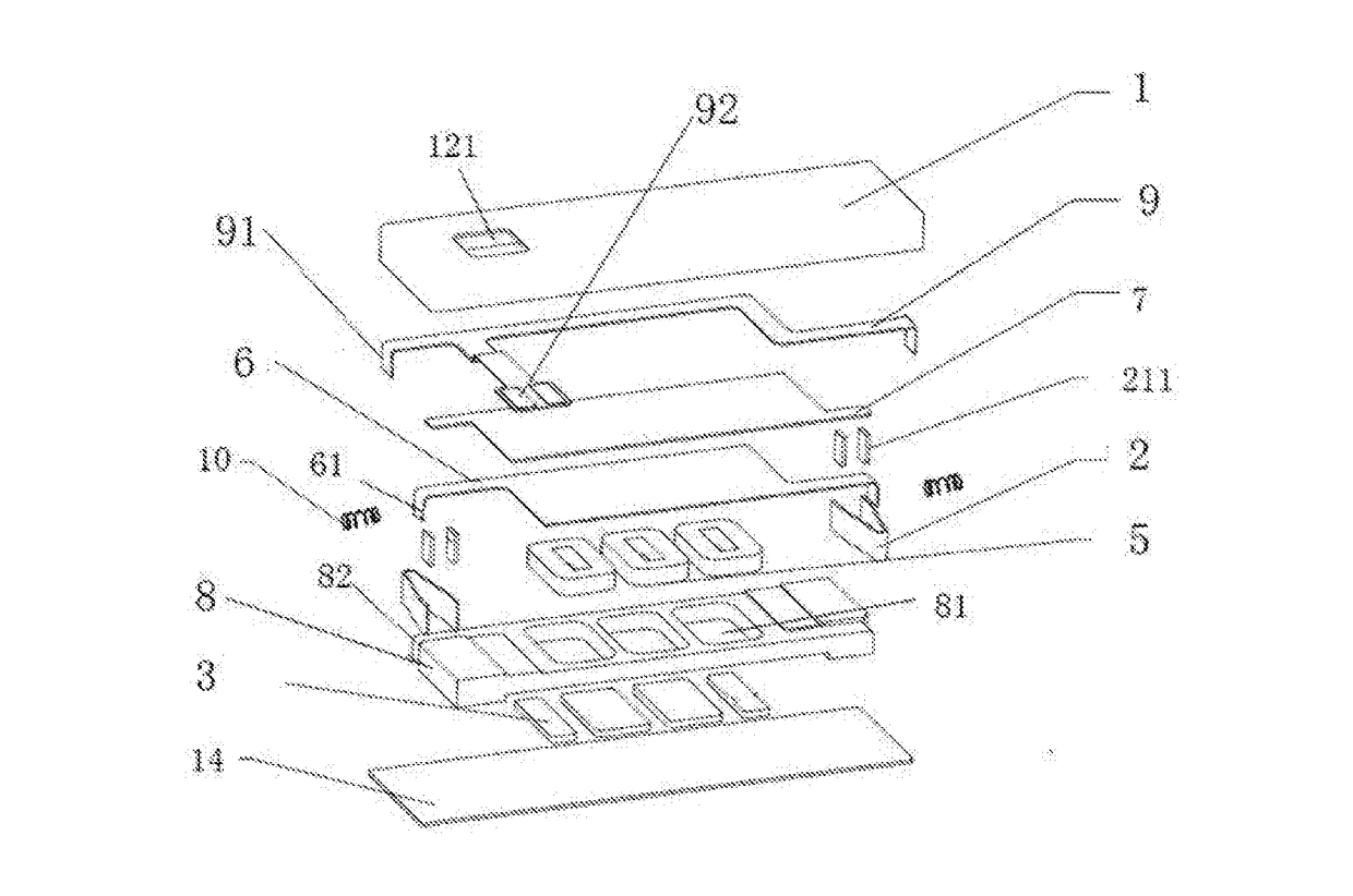
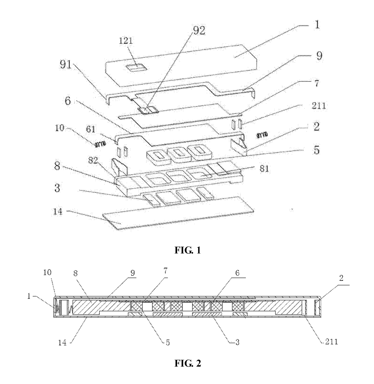
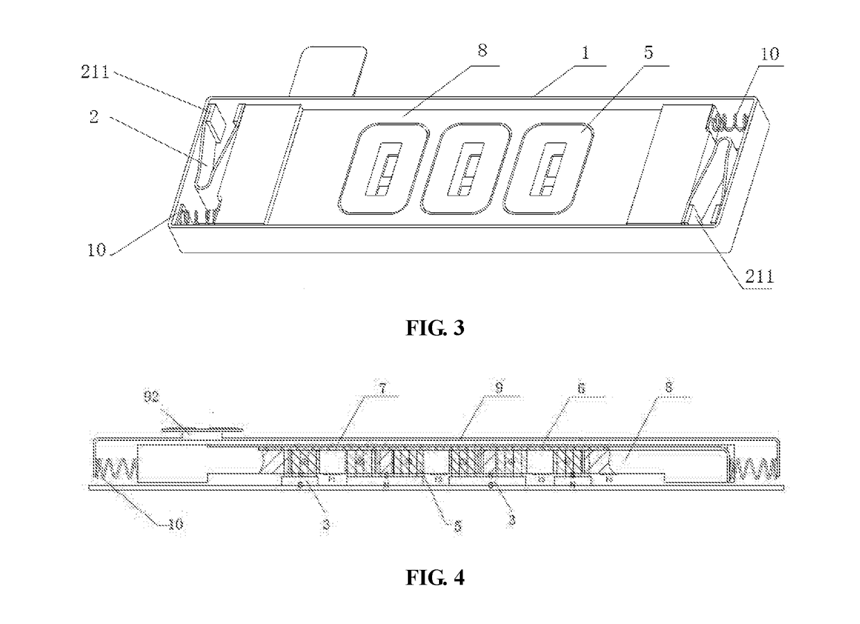
[0040]This embodiment provides a linear motor that comprises a housing 1 having an accommodation space; a mass block 8 suspended in the accommodation space of the housing 1 by an elastic member 2; a coil 5 fastened on the mass block 8; and a magnet 3 fastened on the housing 1 and spaced from the coil 5. When the coil 5 is energized, the electromagnetic interaction between the coil 5 and the magnet 3 generates an electromagnetic force to drive the mass block 8 with the coil 5 to synchronously vibrate back and forth in a substantially horizontal direction.

[0041]In the above-mentioned linear motor, the design route that utilizes the motion of the coil 5 to drive the motion of the mass block 8 is different from the traditional route that utilizes magnet motion to drive mass block motion, thereby the traditional “moving-magnet type” is changed into “moving-coil type” of the present invention. As shown in FIG. 1 or FIG. 4, when the linear motor provided by the present invention is used in...


PUM


Abstract

The present invention provides a linear motor, wherein, a coil is fastened on a mass block that is suspended inside a housing, and a magnet is fastened on the housing and thus does not move during use. In the linear motor of the present invention, the design route that utilizes coil motion to drive mass block motion is different from the traditional route that utilizes magnet motion to drive mass block motion, thereby the traditional “moving-magnet type” is changed into “moving-coil type” of the present invention. When the linear motor provided by the present invention is used in a highly magnetic environment, even if magnetic shield plates for shielding external magnetic induction lines are glued on both outer sides of the housing, because the magnet is fixed stationary itself, no vertical deviation of the magnet due to influence of the shield plates like in the prior art occurs. Meanwhile, even if the magnetic shield plates exert vertical forces on the coil, because such forces exerted by the shield plates on the coil are very small, they are hardly able to drive the coil to move in the vertical direction, and thus no vertical deviation of the coil is caused, so that vibration noise is avoided.

Description

CROSS REFERENCE[0001]This application is based upon and claims priority to Chinese Patent Application No. 201610202883.3 filed on Mar. 31, 2016 and titled “A LINEAR MOTOR”, the entire content of which is incorporated herein by reference.TECHNICAL FIELD[0002]The present invention relates to a horizontal vibration micro motor, which pertains to the technical field of linear vibration motors.BACKGROUND TECHNOLOGY[0003]Portable consumer electronic products such as mobile phones, tablet computers and handheld game consoles are becoming more and more popular with consumers. These electronic products normally use vibration signal as feedback information, for example, mobile phones have incoming call reminder, and handheld game consoles have vibration feedback. The vibration feedback function has become the most important application of vibration motors in the field of consumer electronics.[0004]The structure of a linear vibration motor in prior art is as follows: a suspension component is ...

Claims


Application Information

Patent Timeline
Patent Type & Authority Applications(United States)
IPC IPC(8): H02K33/18H02K5/22H02K5/04
CPCH02K33/18H02K5/225H02K5/04H02K33/02H02K3/52
Inventor JIN, SHAOPINGFANG, SHAOBINCHEN, SHI
Owner JINLONG MACHINERY & ELECTRONICS CO LTD
Why Eureka
Try Eureka