Scalable data access system and methods of eliminating controller bottlenecks

Active Publication Date: 2017-10-12
RADOVANOVIC BRANISLAV
View PDF2 Cites 14 Cited by
  • Summary
  • Abstract
  • Description
  • Claims
  • Application Information

AI Technical Summary

Benefits of technology

[0009]Furthermore, to accelerate execution of write requests and to improve reliability and resiliency, the new nFE_SAN controller hardware design enables a second copy of write data to be maintained locally without a need to first traverse the network fabric and store the second copy of the data on (n)BE_SAN controller(s). In order to prevent single-points-of-failure, the nFE_SAN controller design includes two independent write-back cache memory buffers, each with corresponding processing, network-interface, and power components. Thus, a single nFE_SAN controller card has two operationally independent controllers, FE_SAN controller and redundant nFE_

Problems solved by technology

Thus, since 1980, the CPU performance has increased over quarter of a million times while the performance of legacy SAN systems (many of which are Redundant Array of Independent Disks (RAID) systems) has improved only about 12 times. Therefore, it is clear that in a computer system there is a growing I/O performance gap between compute and storage performance, which may limit the maximum achievable utilization of such unbalanced computer systems.
Even with new advances in Flash Memory and Solid-State Drive (SSD) technology, the data access speed fails to match performance advances in CPU and memory technologies.
Legacy SAN and RAID technologies available today are unable to meet performance requirements and, with prohibitively high cost, are out of reach for the majority of the small and some medium size businesses.
However, such approach introduces other issues such as insufficient storage I/O performance, system and network administration, fault tolerance,

Method used


Image

  • Scalable data access system and methods of eliminating controller bottlenecks
  • Scalable data access system and methods of eliminating controller bottlenecks
  • Scalable data access system and methods of eliminating controller bottlenecks

Examples


Embodiment Construction

” message can be sent to the host.

[0028]FIG. 17 represents a dataflow diagram of write operations showing time saved and overlap times of write operations using the present system. Because two copies of the data are maintained by the nFE_SAN controller “COMMAND COMPLETE” message can be returned to the host as soon as data transfer from the host is done and write lock(s) acquired from (n)BE_SAN controller(s).

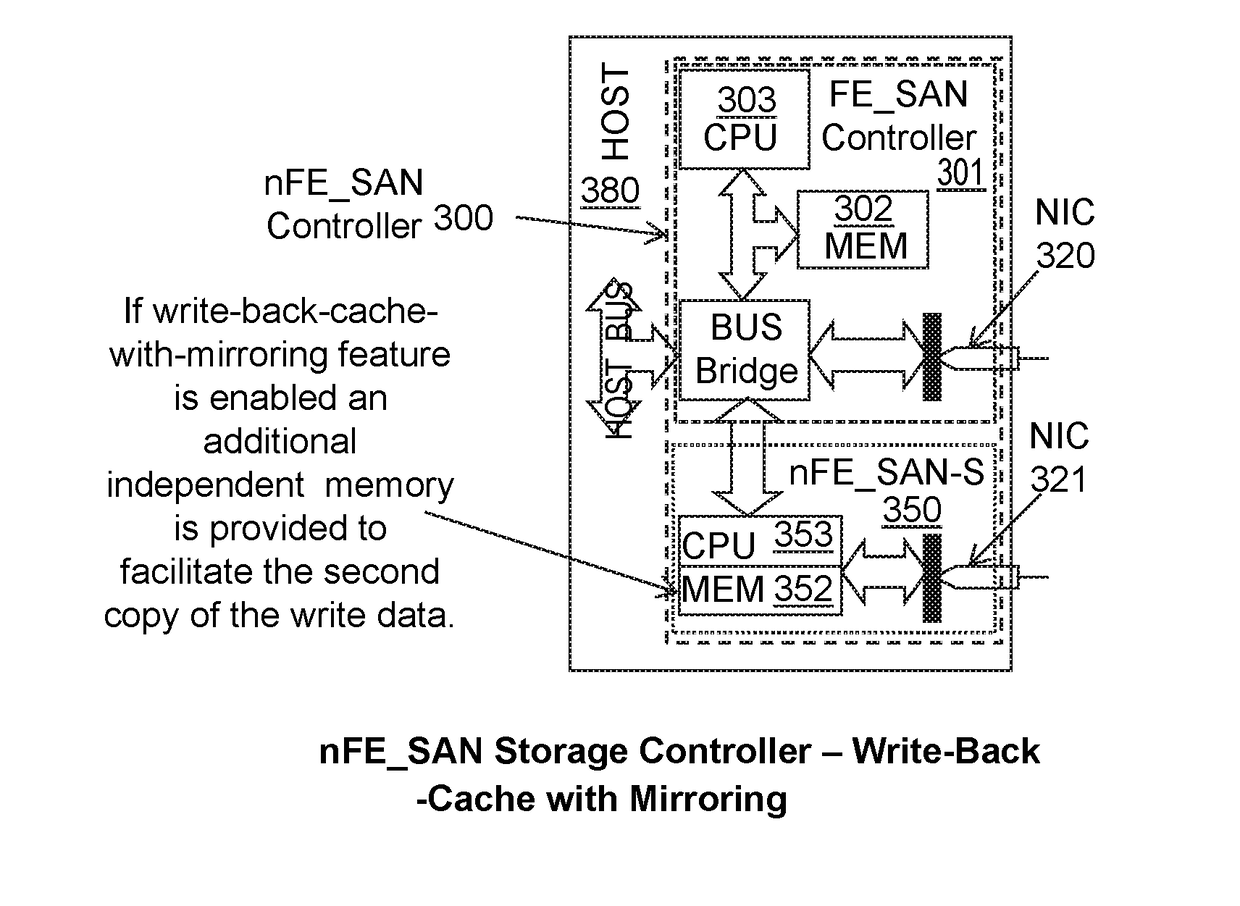
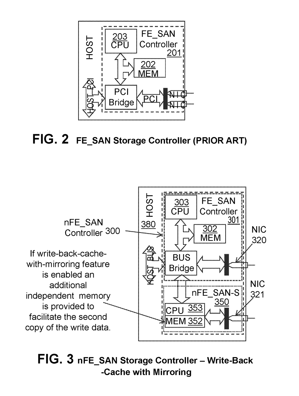
[0029]FIG. 18 depicts Data Access System with first and second cache 1812 and 1818, first and secondary power system 1810 and 1816, first and second network interface 1814 and 1820, and first and secondary processor 1824 and 1826 together form an nFE_SAN controller as herein described.

DETAILED DESCRIPTION OF THE EMBODIMENTS

[0030]FIGS. 3, 3a, 3b, 6, 7, 8, 9, 10, 11, 12, 13, 14, 15, 17, and 18 present a system. There are two parts to this system. FIGS. 3, 3a, 6, 7, and 17 reveal improvements over the prior FE_SAN controller of U.S. Pat. No. 9,118,698, FIG. 3b depicts improvements o...


PUM


Abstract

A data access system has host computers having front-end controllers nFE_SAN connected via a bus or network interconnect to back-end storage controllers nBE_SAN, and physical disk drives connected via network interconnect to the nBE_SANs to provide a distributed, high performance, policy based or dynamically reconfigurable, centrally managed, data storage acceleration system. The hardware and software architectural solutions eliminate BE_SAN controller bottlenecks and improve performance and scalability. In an embodiment, the nBE_SAN (BE_SAN) firmware recognize controller overload conditions, informs Distributed Resource Manager (DRM), and, based on the DRM provided optimal topology information, delegates part of its workload to additional controllers. The nFE_SAN firmware and additional hardware using functionally independent and redundant CPUs and memory that mitigate single points of failure and accelerates write performance. The nFE_SAN and FE_SAN controllers facilitate Converged I/O Interface by simultaneously supporting storage I/O and network traffic.

Description

RELATED APPLICATIONS[0001]This application claims priority to U.S. provisional patent application 62 / 320,349 filed Apr. 8, 2016 (Attorney Docket No. 579645). This application is also related generally to improvements on the storage technology described in U.S. patent application Ser. No. 15 / 173,043 (Attorney Docket No. 581596), which in turn claims priority to U.S. patent application Ser. No. 11 / 292,838 (Attorney Docket No. 521578) and U.S. patent application Ser. No. 14 / 252,838 (now U.S. Pat. No. 9,527,190); the contents of all the aforementioned patent applications and patents are incorporated herein by reference.BACKGROUND OF THE INVENTION[0002]This document generally relates to the field of storage controllers and Storage Area Network (SAN) systems. The goal for this innovative storage technology is to boost performance by accelerating data access speed while improving overall datacenter efficiency to produce immediate saving in power, cooling costs, and floor space.[0003]Accord...

Claims


Application Information

Patent Timeline
IPC IPC(8): G06F3/06G06F12/0806
CPCG06F3/061G06F12/0806G06F2212/62G06F3/065G06F3/067G06F3/0625G06F12/0804G06F12/0868G06F2212/1016G06F2212/1032G06F2212/263G06F2212/286G06F2212/502G06F2212/601G06F3/0634G06F3/0635Y02D10/00
Inventor RADOVANOVIC, BRANISLAV
Owner RADOVANOVIC BRANISLAV
Why Eureka
Try Eureka