Out-of-band coupled antenna combined by fine-and-straight antenna and bow-tie antenna
Active Publication Date: 2017-10-12
BEIHANG UNIV
View PDF0 Cites 0 Cited by
Summary
Abstract
Description
Claims
Application Information
AI Technical Summary
This helps you quickly interpret patents by identifying the three key elements:
Problems solved by technology
Method used
Benefits of technology
Benefits of technology
The present invention describes an out-of-band coupling antenna that improves the separation between a fine-and-straight antenna and a bow-tie antenna by loading inductance on the bow-tie antenna. This reduces out-of-band coupling between the two antennas, resulting in improved performance and a wider operating frequency range. The invention also addresses problems related to current loading fail to pass through the inductance by introducing gaps in a cooper covering layer. Additionally, changing the size of the antenna provides a simple method to regulate the suppressing frequency of the combined antenna.
Problems solved by technology
With the broadband antenna research has becoming a hot spot, the out-of-band coupled problem thereof gradually appears.
The numerical method includes the difference method, Domain finite difference method (FDTD), moment method (MOM), finite element method (FEM) and so on, which not only solves the electromagnetic problem of complex shape solving domain, but also has a fast calculation speed and a wide application range to give the exact solution to the engineering problem, but cannot explain the object from the physical mechanism, and thus is not suitable for designing the antenna according to specific requirements.
For the broadband antenna, when the load suppression is carried out on the bow-tie antenna by using the characteristic mode analysis, since the current distribution of the bow-tie antenna is distributed over the entire antenna and variation of the current distribution cannot be achieved by loading at a certain position, thus its non-operation mode cannot be suppressed, so the conventional method fails.
Method used
Image
Click on the blue label to locate the original text in one second.
Reading with bidirectional positioning of images and text.
Examples
embodiment 1
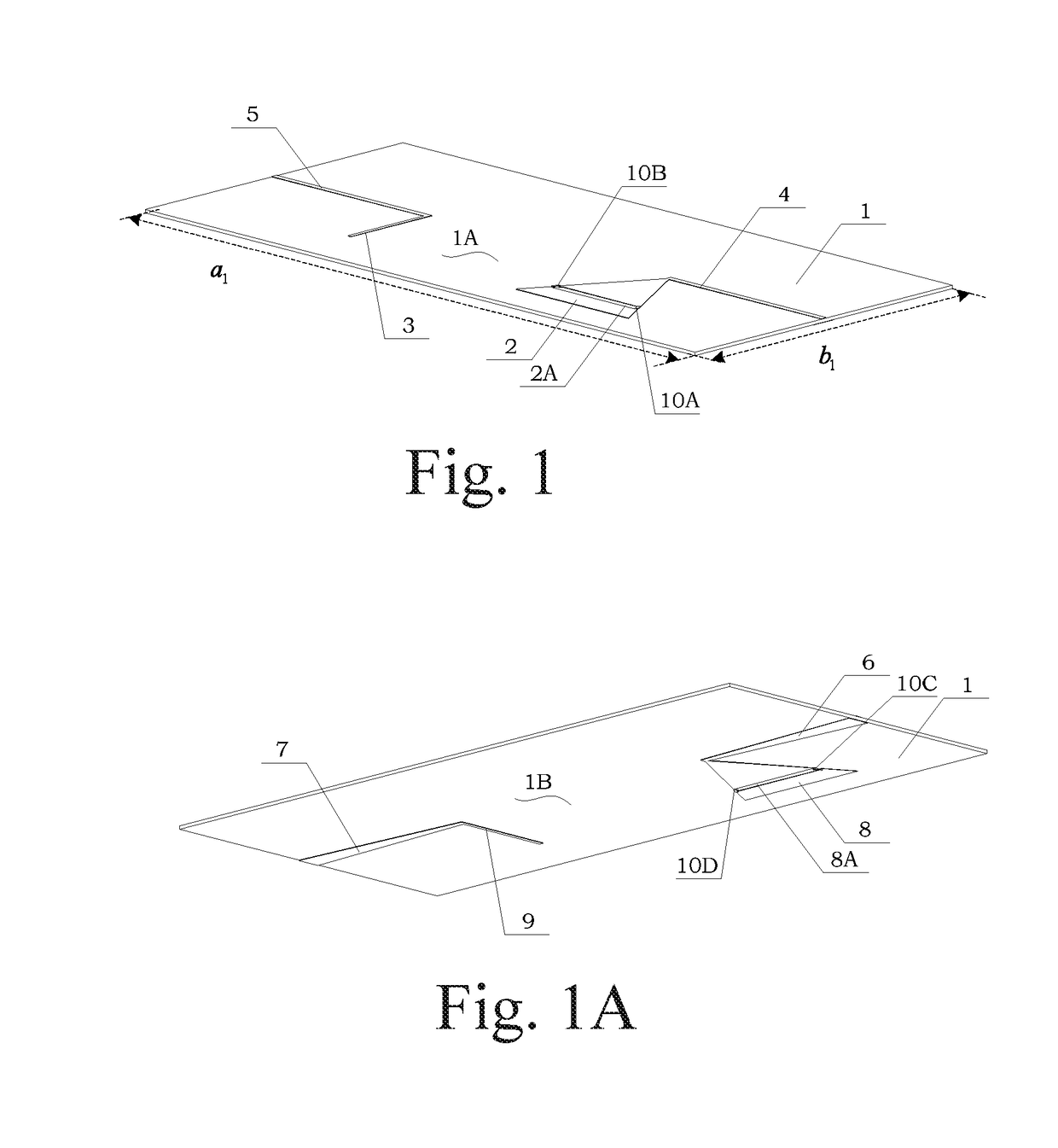
[0054]A thickness of cooper pouring of the radiation elements and the feeder lines manufactured by a cooper pouring technique is 0.0035 cm. In the Embodiment 1, a size of the dielectric slab is: a1=175 cm, b1=82 cm; and a height of the dielectric slab is 0.08 cm.
[0055]A size of the fine-and-straight antenna in the Embodiment 1 is: a3=a9=1 cm, b3=b9=43 cm, a5=a7=50 cm, b5=b7upper=1.5 cm and b7lower=6 cm.
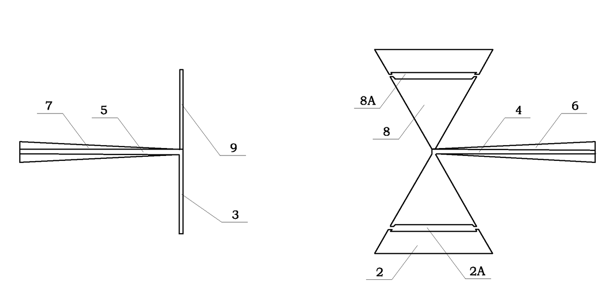
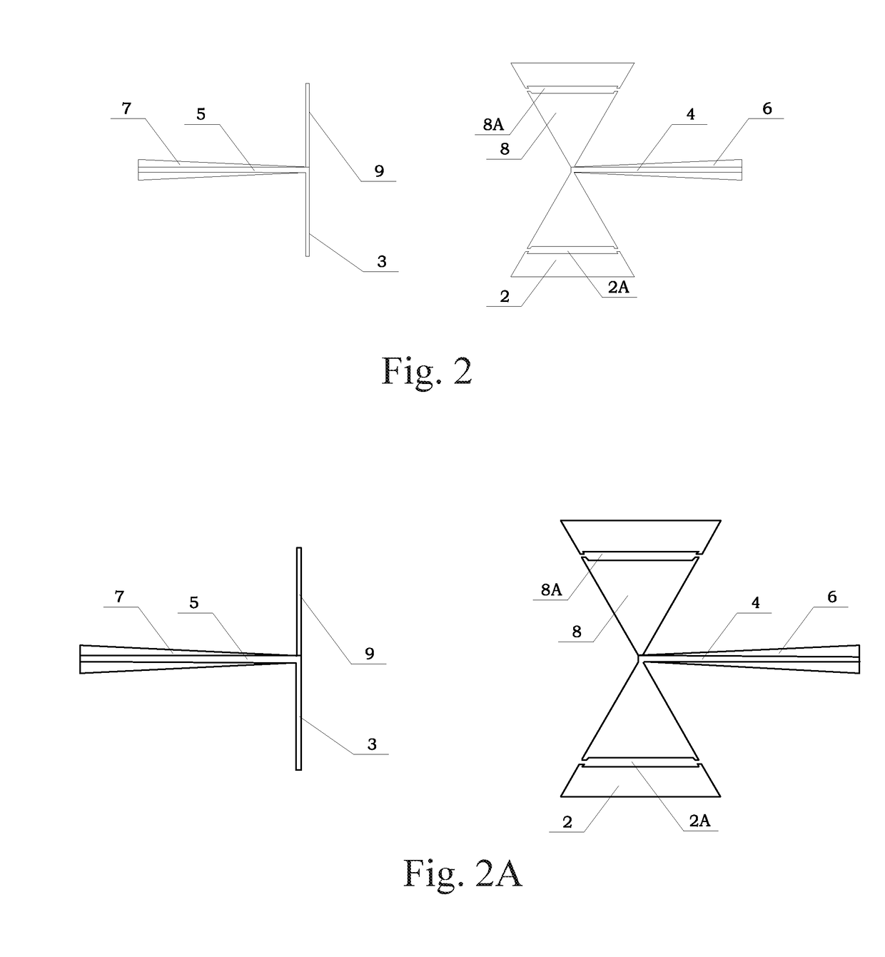
[0056]In the embodiment 1, a size of the bow-tie antenna, i.e., the AA radiation element 2 and the AB radiation element 8 are in cooper pouring configuration of isosceles trapezoidal, is: a4=a6=50 cm, b4=b6upper=1.5 cm, b6lower=6 cm, a2upper=a8upper=1 cm, a2lower=a8lower=35.6 cm, b2=b8=31 cm, a2groove=a8groove=2 cm. The cutting position of the A isolation groove 2A is on three quarters of b2, i.e., 23.25 cm. The cutting position of the B isolation groove 8A is on three quarters of b8, i.e., 23.25 cm.
[0057]In the Embodiment 1, S-parameter is utilized for performance evaluation in. Dott...
embodiment 2
[0063]A thickness of cooper pouring of the radiation elements and the feeder lines manufactured by a cooper pouring technique is 0.0035 cm. Structural size of the Embodiment 2 is identical to the Embodiment 1, and the only difference lies in the shape of the trapezoidal of the bow-tie antenna, i.e., the shape of the trapezoidal of the AC radiation element 20 and the AD radiation element 80 has a cathetus and a bevel edge (See FIG. 6).
[0064]In the Embodiment 2, S-parameter is utilized for performance evaluation in. Dotted line in the Figure represents a conventional antenna wherein inductance is not loaded on the AC radiation element 20 and the AD radiation element 80. The solid lines represent the antennas designed in the Embodiment 2.
[0065]The parameter S11 represents the operation performance of the bow-tie antenna, wherein the performance before and after loading the inductance and at a working frequency of 200 MHz is not basically changed.
[0066]The present invention uses S12 to ...
PUM
Abstract
An out-of-band coupled antenna combined by fine-and-straight antenna and bow-tie antenna is provided, including: a dielectric slab (1), an AA radiation element (2) provided on an upper plate (1A) of the dielectric slab (1) by a , a cooper pouring process, a BA radiation element (3), an A feeder line (4) and a B feeder line (5); an AB radiation element (8) provided on a lower plate (1B) of the dielectric slab (1), a BB radiation element (9), a C feeder line feeder (6) and a D feeder line (7); a first sensor (10A) and a second sensor (10B) which are connected on the AA radiation element (2); a third sensor (10C) and a fourth sensor (10D) which are connected on the AB radiation element (8). The antenna is capable of suppressing out-of-band coupling between indication elements to improve the separation degree.
Description
CROSS REFERENCE OF RELATED APPLICATION[0001]The present application claims priority under 35 U.S.C. 119(a-d) to CN 201610481737.9, filed Jun. 27, 2016.BACKGROUND OF THE PRESENT INVENTIONField of Invention[0002]The present invention relates to an out-of-band coupling suppression antenna and more particularly to a combined antenna for multiplying a fine-and-straight antenna and a bow-tie antenna.Description of Related Arts[0003]At present, due to the characteristics of the capacity of keeping a good balance of instantaneous bandwidth, signal conformal, effective radiation and other aspects, bow-tie antennas are widely applied in antennas radiated by narrow pulse signals. In addition, since the bow-tie antenna is light easy to manufacture, it also has important application in other fields. With the rapid development of science and technology and the popularity of broadband communication equipments, the broadband technology of the antennas is also developing constantly. With the increas...
Claims
Application Information
Patent Timeline
Application Date:The date an application was filed.
Publication Date:The date a patent or application was officially published.
First Publication Date:The earliest publication date of a patent with the same application number.
Issue Date:Publication date of the patent grant document.
PCT Entry Date:The Entry date of PCT National Phase.
Estimated Expiry Date:The statutory expiry date of a patent right according to the Patent Law, and it is the longest term of protection that the patent right can achieve without the termination of the patent right due to other reasons(Term extension factor has been taken into account ).
Invalid Date:Actual expiry date is based on effective date or publication date of legal transaction data of invalid patent.

