Class-D amplifier of BTL output type using filter coil and low-pass filter

Inactive Publication Date: 2005-02-15
YAMAHA CORP
View PDF8 Cites 9 Cited by
  • Summary
  • Abstract
  • Description
  • Claims
  • Application Information

AI Technical Summary

Benefits of technology

Thus, it is possible to effectively suppress inductive coupling between adjacent coils, and it is possible to realize reduction

Problems solved by technology

Since the aforementioned class-D amplifier requires four coils independently for use in the four low-pass filters for eliminating carrier frequency components of PWM signals corresponding to BTL outputs thereof, there are problems in that a considerable amount of the cost

Method used


Image

  • Class-D amplifier of BTL output type using filter coil and low-pass filter
  • Class-D amplifier of BTL output type using filter coil and low-pass filter
  • Class-D amplifier of BTL output type using filter coil and low-pass filter

Examples


Example

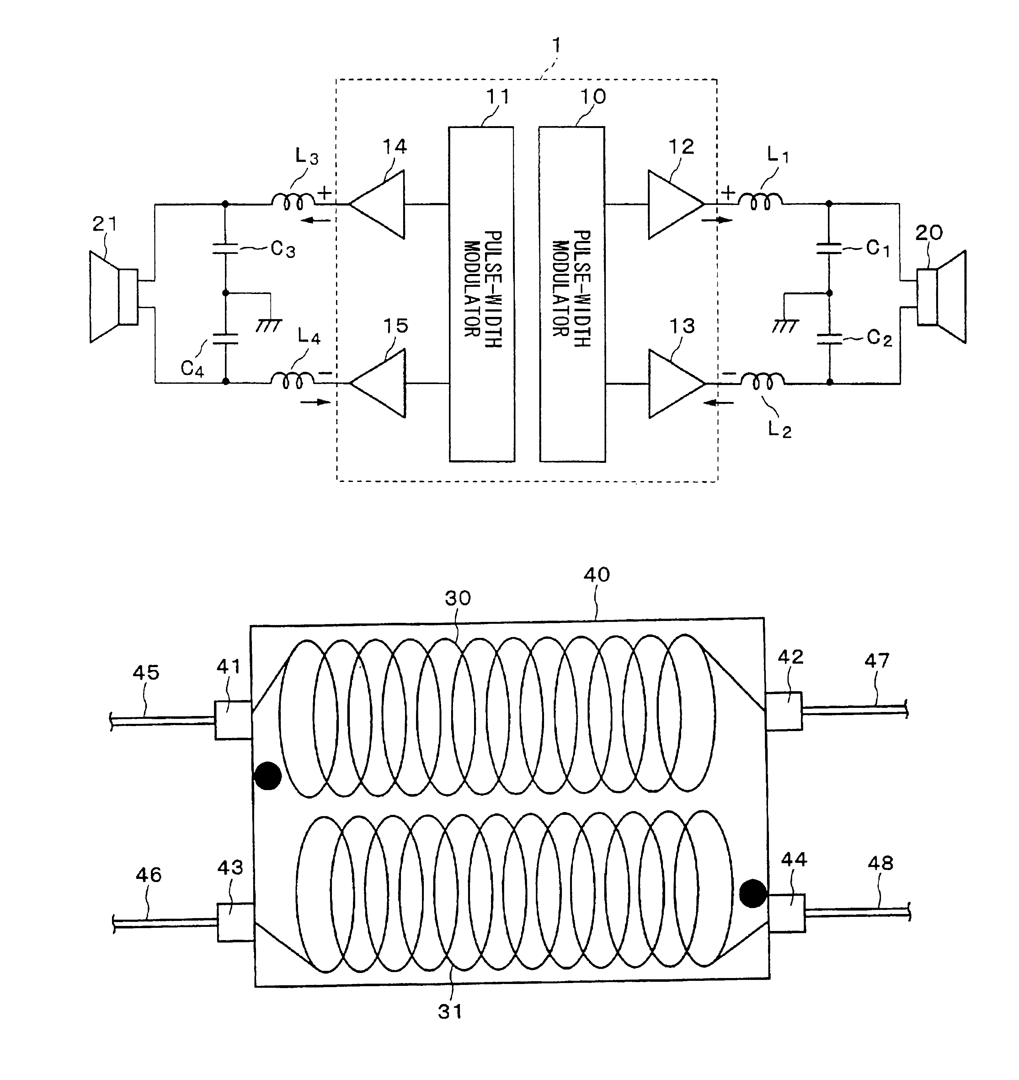
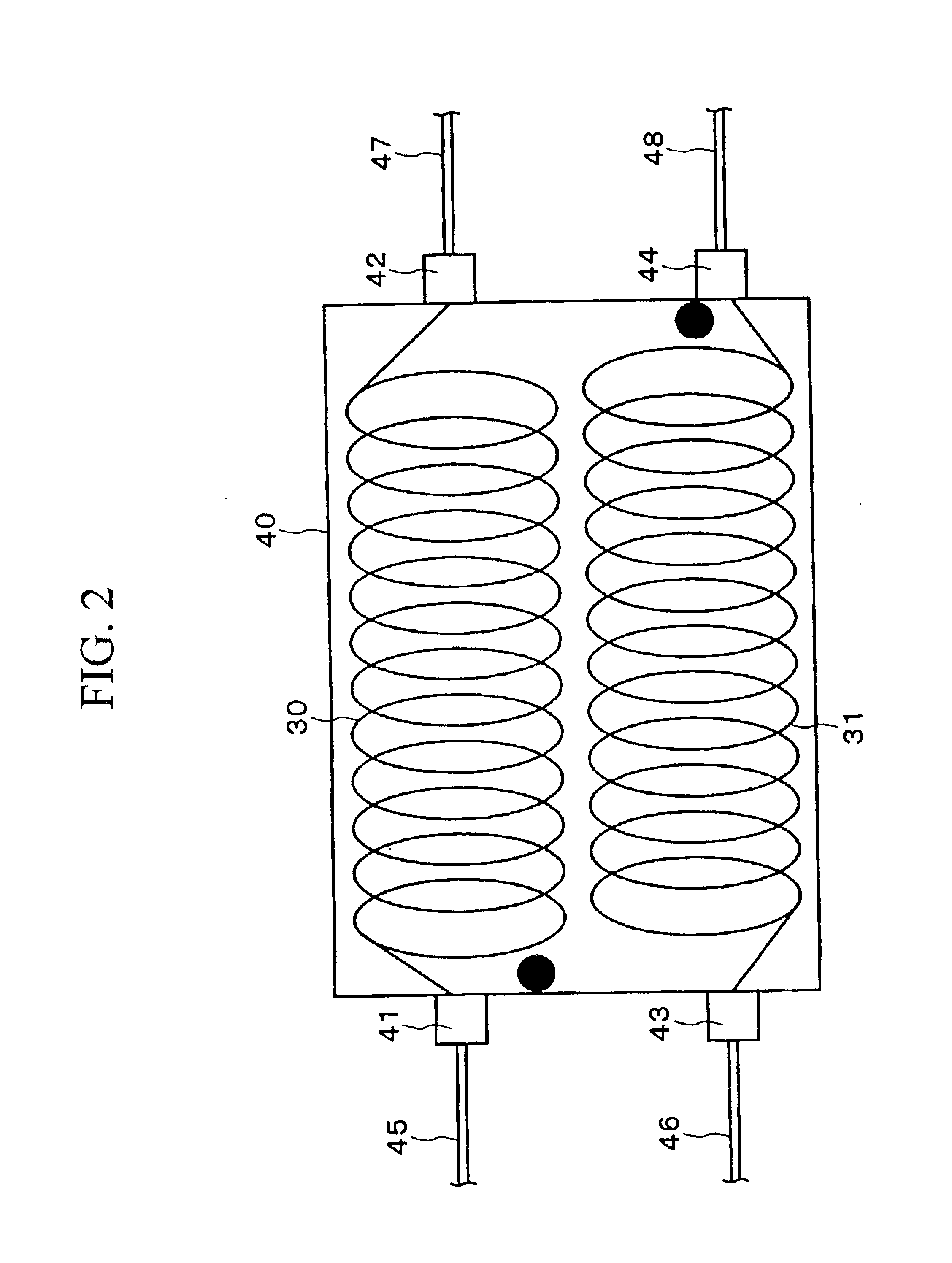
The filter coil of the first embodiment incorporates an even number of coils, each having the same inductance, which are arranged adjacent to each other along axial directions thereof, wherein the adjacent coils differ from each other in winding directions. That is, plural pairs of the aforementioned coils are arranged in a single package. Thus, it is possible to realize reduction of installed areas of coils and reduction of the cost in manufacture of filter coils incorporating coils for use in low-pass filters connected with BTL outputs of class-D amplifiers.

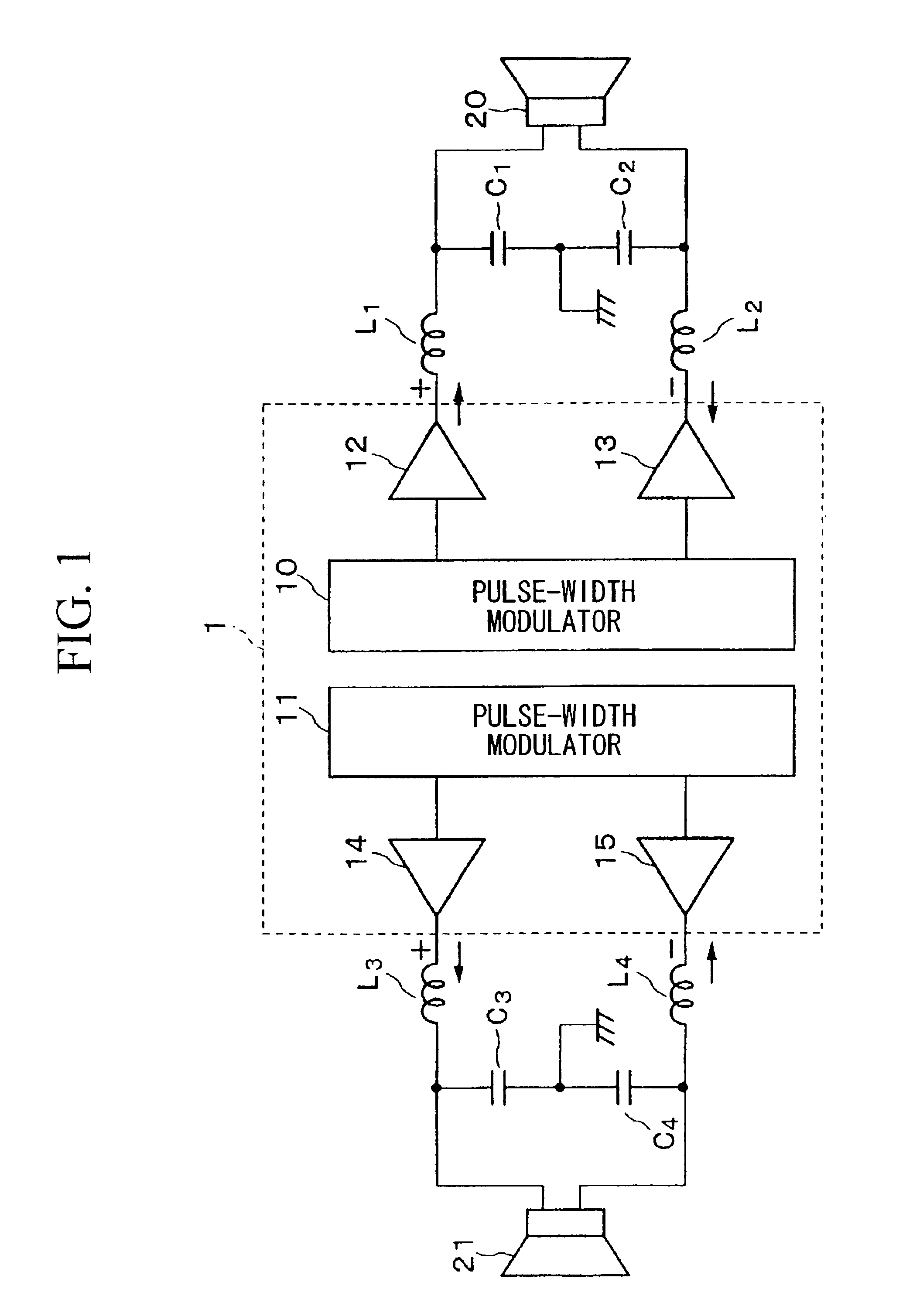
In the class-D amplifier of the BTL output type, the positive polarity output and the negative polarity output both have the same magnitude (or amplitude) but differ from each other in phases by 180°. Therefore, a pair of coils, which differ from each other in winding directions, respectively produce magnetic fluxes in opposite directions, causing cancellation of magnetic fluxes and preventing occurrence of inductive coupling t...

Example

Next, a description will be given with respect to a filter coil in accordance with the second embodiment of the invention with reference to FIG. 5. That is, the filter coil of the second embodiment provides coils that constitute low-pass filters for eliminating carrier frequency components in BTL outputs of a class-D amplifier.

Specifically, a pair of coils 100 and 101, each having the same inductance, which differ from each other in winding directions are arranged to adjoin together along axial directions thereof in a package 110. Ends of the coil 100 are connected with terminals 130 and 131, and ends of the coil 101 are connected with terminals 132 and 133.

In addition, a pair of coils 102 and 103, each having the same inductance, which differ from each other in winding directions are arranged to adjoin together along axial directions thereof in the package 110. Ends of the coil 102 are connected with terminals 134 and 135, and ends of the coil 103 are connected with terminals 136 a...

Example

Next, a filter coil of the third embodiment of the invention will be described with reference to FIG. 6. The filter coil of the third embodiment incorporates coils for use in low-pass filters for eliminating carrier frequency components in BTL outputs of the class-D amplifier. In FIG. 6, a pair of coils 200 and 201, each having the same inductance, which differ from each other in winding directions are respectively wound about a core 210A of a bobbin 210 along its axial direction.

For the sake of the convenience, FIG. 6 shows only a single pair of coils 200 and 201 wound about the core 210A of the bobbin 210. Of course, it is possible to arrange plural pairs of coils wound about the core 210A of the bobbin 210.

Suppose that the coils 200 and 201 contained in the filter coil of FIG. 6 are used as the inductors L1 and L2 for use in the two low-pass filters connected with BTL outputs of the class-D amplifier 1 shown in FIG. 1. In this case, a first terminal 200A of the coil 200 is connec...


PUM


Abstract

A filter coil incorporates coils, each having the same inductance, which differ from each other in winding directions and are used for low-pass filters for eliminating carrier frequency components in BTL outputs of a class-D amplifier, which performs pulse-width modulation and amplification on input signals. A pair of coils can be arranged to adjoin together along axial directions thereof in a single package, or plural pairs of coils can be arranged to adjoin together in a single package with intervention of a magnetic shield therebetween. Alternatively, a pair of coils are wound about a single core along its axial direction with intervention of a magnetic shield therebetween. Thus, it is possible to effectively suppress inductive coupling between adjacent coils, and it is possible to realize reduction of installed areas of coils and reduction of the cost in manufacture of filter coils as well as prevention of unwanted radiation.

Description

BACKGROUND OF THE INVENTION1. Field of the InventionThis invention relates to class-D amplifiers of Bridged Tied Load (BTL) output types, which use filter coils and low-pass filters.2. Description of the Related ArtFIG. 1 shows a typical example of a class-D amplifier of the BTL output type, which acts as an amplifier for driving speakers of two channels (i.e., right and left channels). That is, a class-D amplifier 1 of the BTL output type comprises pulse-width modulators 10 and 11 that produce pulse-width modulated (PWM) signals whose pulse widths match input signal levels, as well as drivers 12 to 15 for driving switching elements (not shown) such as metal-oxide semiconductor (MOS) transistors connected between the positive and negative voltage supplies (not shown).There are provided two-channel speakers 20 and 21, which act as loads for the class-D amplifier 1. In addition, there are provided four low-pass filters (i.e., LC filters), each consisting of a pair of a capacitor (or c...

Claims


Application Information

Patent Timeline
IPC IPC(8): H03F3/217H03F3/20H01F17/00H03F3/68
CPCH03F3/2173H03F3/217
Inventor MURAMATSU, TOSHIHIKO
Owner YAMAHA CORP
Why Eureka
Try Eureka