MIMO transceiver suitable for a massive-mimo system

a transceiver and mass-produced technology, applied in the field of communication equipment, can solve the problems of increasing the number of antennas, the complexity and relatively high cost of the hardware in the radio-frequency section, and the prohibitive cost of the conventional rf equipment used therein, so as to reduce the size and/or cost of the transceiver

Active Publication Date: 2017-10-19
ALCATEL-LUCENT USA INC
View PDF4 Cites 15 Cited by
  • Summary
  • Abstract
  • Description
  • Claims
  • Application Information

AI Technical Summary

Benefits of technology

[0005]The disclosed transceiver architecture can advantageously provide a reduction of the transceiver size and / or cost and a performance improvement with respect to conventional transceiver architectures on a scale that makes the disclosed transceiver architecture suitable for use in a wide range of emerging wireless devices and systems, such as nodes for the Internet of Things, 5G user equipment, M-MIMO base stations, etc.

Problems solved by technology

A major obstacle to the commercial deployment of massive-MIMO (M-MIMO) systems is the complexity and relatively high cost of the hardware in the radio-frequency (RF) section, which dramatically rise with an increase in the number of antennas.
Since an M-MIMO transceiver can utilize hundreds of antennas, the cost of conventional RF equipment used therein can be prohibitive for commercial applications.

Method used


Image

  • MIMO transceiver suitable for a massive-mimo system
  • MIMO transceiver suitable for a massive-mimo system
  • MIMO transceiver suitable for a massive-mimo system

Examples


Embodiment Construction

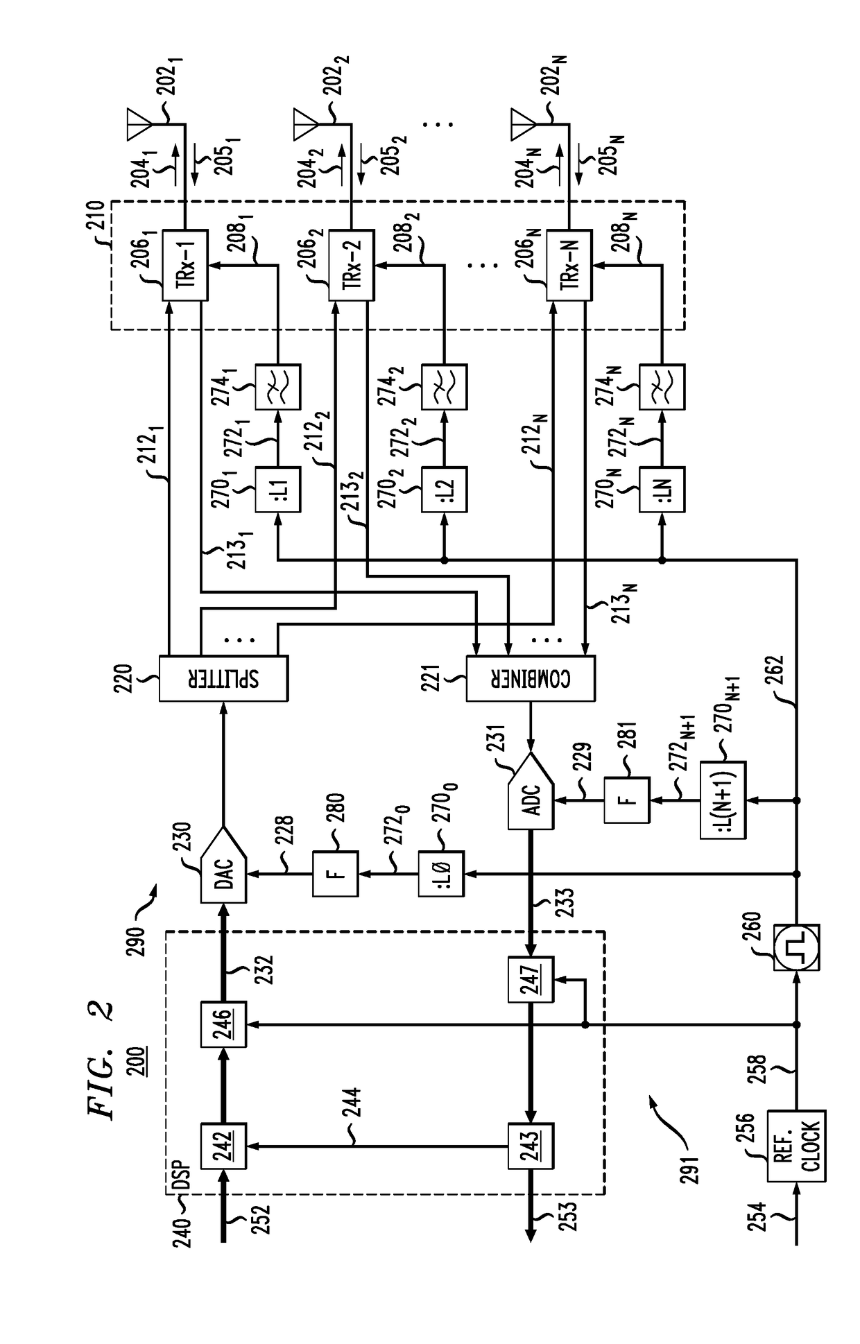
[0004]An embodiment of the disclosed MIMO transceiver uses a single master clock to generate (i) the sampling-clock signal that clocks the analog-to-digital converter in the receiver branch of the transceiver, (ii) the sampling-clock signal that clocks the digital-to-analog converter in the transmitter branch of the transceiver, and (iii) multiple electrical local-oscillator signals that are used in various channels of the transceiver's analog down- and up-converters to translate signals between the corresponding intermediate-frequency and RF bands. The MIMO transceiver may employ a plurality of interconnected frequency dividers configured to variously divide the master-clock frequency to generate the two sampling-clock signals and the multiple local-oscillator signals in a manner that causes these signals to have different respective frequencies. In embodiments designed for operating in the millimeter-wave (or centimeter-wave) band, the MIMO transceiver may also employ a frequency ...


PUM


Abstract

An embodiment of the disclosed MIMO transceiver uses a single master clock to generate (i) the sampling-clock signals for the analog-to-digital and digital-to-analog converters and (ii) the multiple electrical local-oscillator signals that are used in various channels of the transceiver's analog down- and up-converters to translate signals between the corresponding intermediate-frequency and RF bands. The MIMO transceiver may employ a plurality of interconnected frequency dividers configured to variously divide the master-clock frequency to generate the sampling-clock signals and the multiple local-oscillator signals in a manner that causes these signals to have different respective frequencies. In embodiments designed for operating in the mmW band, the MIMO transceiver may also employ a frequency multiplier configured to multiply the master-clock frequency to generate an additional local-oscillator signal for translating signals between the mmW and RF bands.

Description

FIELD[0001]The present disclosure relates to communication equipment and, more specifically but not exclusively, to multiple-input / multiple-output (MIMO) wireless transceivers.DESCRIPTION OF THE RELATED ART[0002]This section introduces aspects that may help facilitate a better understanding of the disclosure. Accordingly, the statements of this section are to be read in this light and are not to be understood as admissions about what is in the prior art or what is not in the prior art.[0003]A major obstacle to the commercial deployment of massive-MIMO (M-MIMO) systems is the complexity and relatively high cost of the hardware in the radio-frequency (RF) section, which dramatically rise with an increase in the number of antennas. Since an M-MIMO transceiver can utilize hundreds of antennas, the cost of conventional RF equipment used therein can be prohibitive for commercial applications. As a result, practical solutions directed at reducing the complexity and cost of the M-MIMO equip...

Claims


Application Information

Patent Timeline
Patent Type & Authority Applications(United States)
IPC IPC(8): H04B7/04H04J1/05H04J1/08H04B7/06H04W88/08
CPCH04B7/0452H04B7/0626H04W88/08H04J1/05H04J1/08H04B1/0082H04B1/405H04B7/0413
Inventor KURCHUK, BORIS A.
Owner ALCATEL-LUCENT USA INC
Why Eureka
Try Eureka