Exhaust gas purification catalyst

a technology of exhaust gas and catalyst, which is applied in the direction of physical/chemical process catalyst, metal/metal-oxide/metal-hydroxide catalyst, separation process, etc., can solve the problems of exhaust emissions deterioration and excessive pressure loss, and achieve better suppressed pressure loss, efficient utilization, and improved efficiency

Active Publication Date: 2017-10-26
CATALER CORP +1
View PDF2 Cites 18 Cited by
  • Summary
  • Abstract
  • Description
  • Claims
  • Application Information

AI Technical Summary

Benefits of technology

[0017]In another preferred aspect of the herein disclosed exhaust gas purification catalyst, the length (average length) L1 of the first catalyst layer is at least 20% and not more than 90% of the Lw. The exhaust gas purification capacity can be even more favorably expressed by disposing the catalyst metal in a section that is at least 20% of the total length Lw in the extending direction of the partition from the exhaust gas inflow-side end. In addition, increases in the pressure loss can be better suppressed by having L1 be not more than 90% of the Lw.
[0018]In another preferred aspect of the herein disclosed exhaust gas purification catalyst, the length (average length) L2 of the second catalyst layer is at least 20% and not more than 90% of the Lw. The exhaust gas purification capacity can be even more favorably expressed by disposing the catalyst metal in a section that is at least 20% of the total length Lw in the extending direction of the partition from the exhau

Problems solved by technology

An excessive rise in the pressure loss occurred when the surface of such an entrance cell was coated by the catalyst layers.
It was found that as a cons

Method used


Image

  • Exhaust gas purification catalyst
  • Exhaust gas purification catalyst
  • Exhaust gas purification catalyst

Examples


example 1

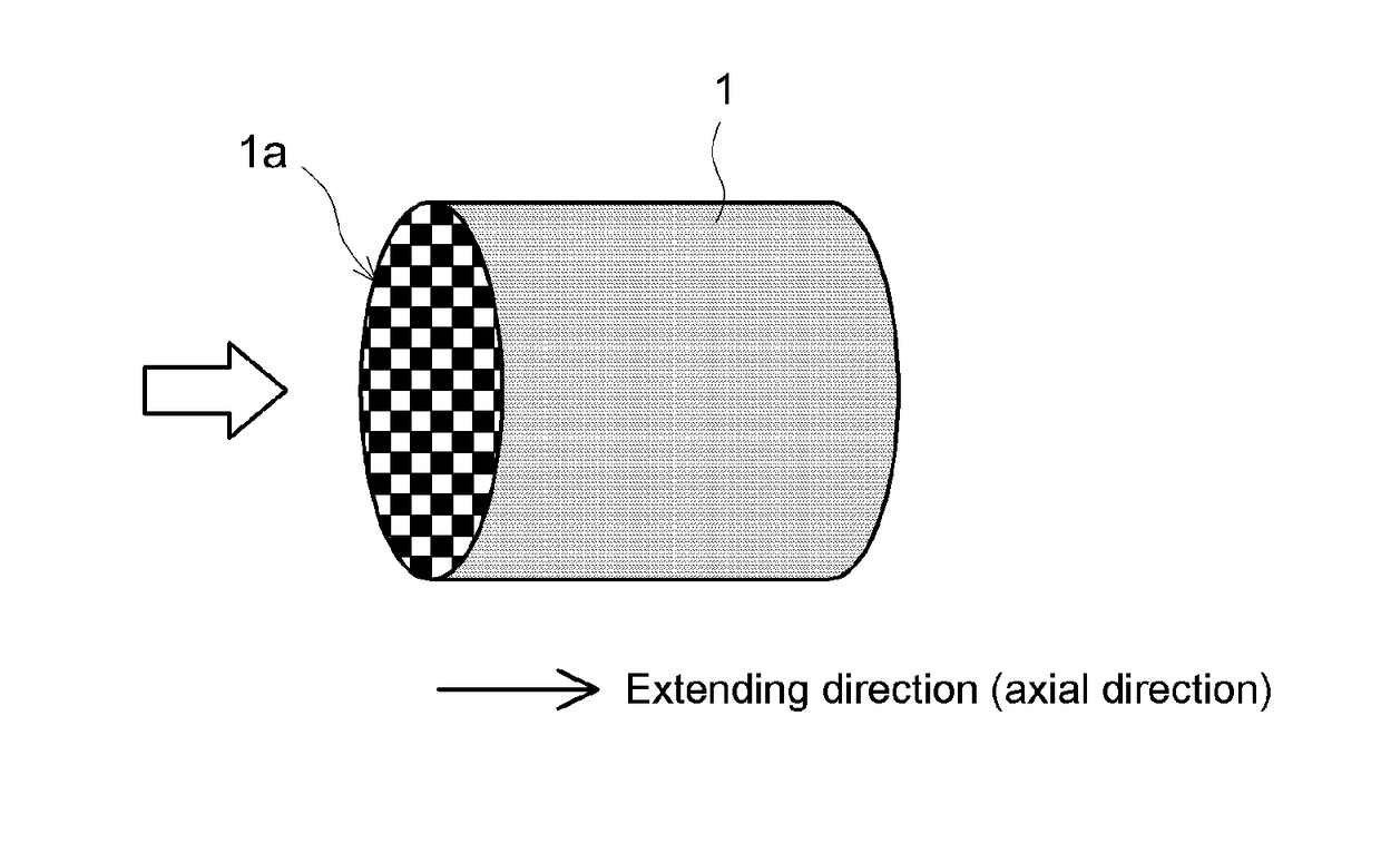
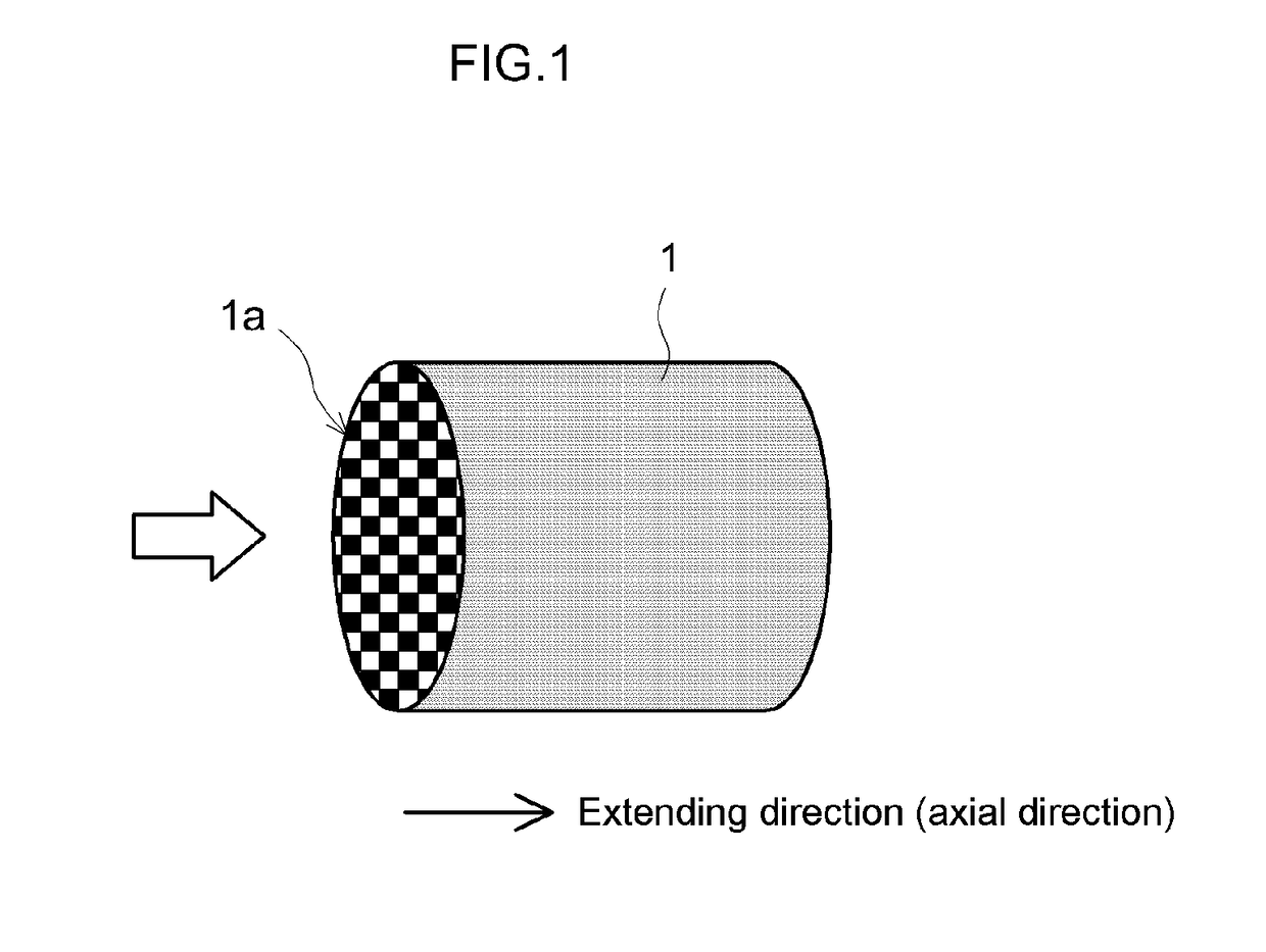
[0055]A cordierite honeycomb substrate having a cell count of 300 cpsi (cells per square inch), a volume (refers to the bulk volume of the whole article, also including the volume of the cell flow paths) of 0.9 L, a total length of 105 mm, an outer diameter of 103 mm, a partition thickness of 0.3 mm, and a porosity of 59% was prepared as the substrate.

[0056]An appropriate amount of pure water was then mixed with 40 g of Al2O3 powder (γ-Al2O3) as the support and with an appropriate amount of an aqueous rhodium solution having an Rh content of 0.2 g as the catalyst metal. The obtained mixture was stirred and mixed and then dried and baked (500° C., 1 hour) to obtain a catalyst metal-loaded powder in which Rh was loaded on the Al2O3 powder. A catalyst layer-forming slurry was prepared by mixing this catalyst metal-loaded powder with an appropriate amount of pure water and a ceria-zirconia composite oxide solution that provided 60 g of CZ composite oxide after baking.

[0057]This slurry w...

example 2

[0060]An exhaust gas purification catalyst (Example 2) was produced proceeding as in Example 1, but making the length in the extending direction of both the first catalyst layer and the second catalyst layer 50% of the total length Lw in the extending direction of the partition.

example 3

[0061]An exhaust gas purification catalyst (Example 3) was produced proceeding as in Example 1, but making the length in the extending direction of both the first catalyst layer and the second catalyst layer 55% of the total length Lw in the extending direction of the partition. In this example, the first catalyst layer overlaps with the second catalyst layer over a length of 10% of the Lw in the extending direction. That is, in the central region of the partition in the extending direction, the first catalyst layer and the second catalyst layer are stacked in the thickness direction (with an intervening region in which no catalyst layer is formed), thus providing a multilayer structure.


PUM

PropertyMeasurementUnit
Fractionaaaaaaaaaa
Fractionaaaaaaaaaa
Fractionaaaaaaaaaa

Abstract

An exhaust gas purification catalyst that has an excellent exhaust gas purification performance while suppressing pressure loss increases. The exhaust gas purification catalyst is provided with a substrate having a wall-flow structure and having a partition; a first catalyst layer formed, in a region of an interior part of the partition that is in contact with an entrance cell, along the extending direction of the partition from an exhaust gas inflow-side end for less than the total length Lw of the partition; and a second catalyst layer formed, in a region of an interior part of the partition that is in contact with an exit cell, along the extending direction of the partition from the exhaust gas outflow-side end for less than the total length Lw of the partition. The first catalyst layer and the second catalyst layer are configured to partially overlap with each other in the extending direction.

Description

TECHNICAL FIELD[0001]The present invention relates to an exhaust gas purification catalyst that is disposed in an exhaust system of an internal combustion engine. More particularly, the present invention relates to a wall-flow exhaust gas purification catalyst.[0002]This international application claims priority based on Japanese Patent Application 2014-211379 filed Oct. 16, 2014, and the contents of said application are incorporated in their entirety in this Description by reference.BACKGROUND ART[0003]The exhaust gas discharged from an internal combustion engine, e.g., an automotive engine, contains harmful components such as particulate matter (PM), hydrocarbons (HC), carbon monoxide (CO), nitrogen oxides (NOx), and so forth. A wall-flow exhaust gas purification catalyst is used to efficiently remove these exhaust gas components.[0004]A wall-flow exhaust gas purification catalyst are provided with an entrance cell having an open exhaust gas inflow-side end, an exit cell having an...

Claims


Application Information

Patent Timeline
IPC IPC(8): F01N3/28B01D53/94B01J37/02B01J35/04B01J23/46B01J23/44B01J23/42B01J23/10B01J21/04B01J37/08B01J35/00
CPCF01N3/28B01D2255/1025B01J23/464B01J21/04B01J23/10B01J23/42B01J23/44B01J35/0006B01J35/04B01J37/0244B01J37/0236B01J37/088B01D2255/9155B01D2255/9022B01D2255/1021B01D2255/1023B01D53/94F01N3/022F01N3/035F01N3/0222F01N2510/0682B01D53/945B01D2255/2065B01D2255/20715B01D2255/407Y02T10/12
Inventor ONOE, RYOTASAKAGAMI, SHINGOITO, TSUYOSHITAKEUCHI, MASAHIKOMIYOSHI, NAOTOSATO, AKEMI
Owner CATALER CORP
Why Eureka
Try Eureka