Coolant and a method to control the ph and resistivity of coolant used in a heat exchanger

a technology of resistivity and coolant, which is applied in the direction of lighting and heating apparatus, chemical instruments and processes, corrosion prevention, etc., can solve the problems of inconsistency in ph and resistivity of coolant used in heat exchangers, adversely affecting device performance, and low ph of distilled water

Active Publication Date: 2017-10-26
APPLIED MATERIALS INC
View PDF5 Cites 3 Cited by
  • Summary
  • Abstract
  • Description
  • Claims
  • Application Information

AI Technical Summary

Benefits of technology

[0006]Implementations described herein generally relate to substrate processing equipment and more particularly to methods and compositions for temperature control of substrate processing equipment. In one implementation, a method of cooling a processing chamber component is provided. The method comprises introducing an inert purge gas into a supply reservoir containing a coolant to form a treated coolant. The coolant initially comprises deionized water and a water-soluble base. The method further comprises flowing the treated coolant to a processing chamber component to cool the processing chamber component.

Problems solved by technology

These processes are often thermally based and typically involve high process temperatures ranging from, for example, 200 degrees Celsius to 1,600 degrees Celsius, which can result in significant thermal budget issues that adversely affect device performance.
Currently, coolants (e.g., distilled water) used in the heat exchanger suffer from inconsistency in both pH and resistivity.
The pH of distilled water tends to be low (acidic, due to reaction with carbon dioxide (CO2) in the air) and the resistivity is difficult to control depending on the source.
This inconsistency in pH sometimes leads to corrosion of the metal components of the heat exchanger.
For example, as the acidity of the coolant increases the metal corrosion rate also increases.
This metal corrosion can clog the flow path leading to overheating and permanent damage to the component.

Method used


Image

  • Coolant and a method to control the ph and resistivity of coolant used in a heat exchanger
  • Coolant and a method to control the ph and resistivity of coolant used in a heat exchanger
  • Coolant and a method to control the ph and resistivity of coolant used in a heat exchanger

Examples


Embodiment Construction

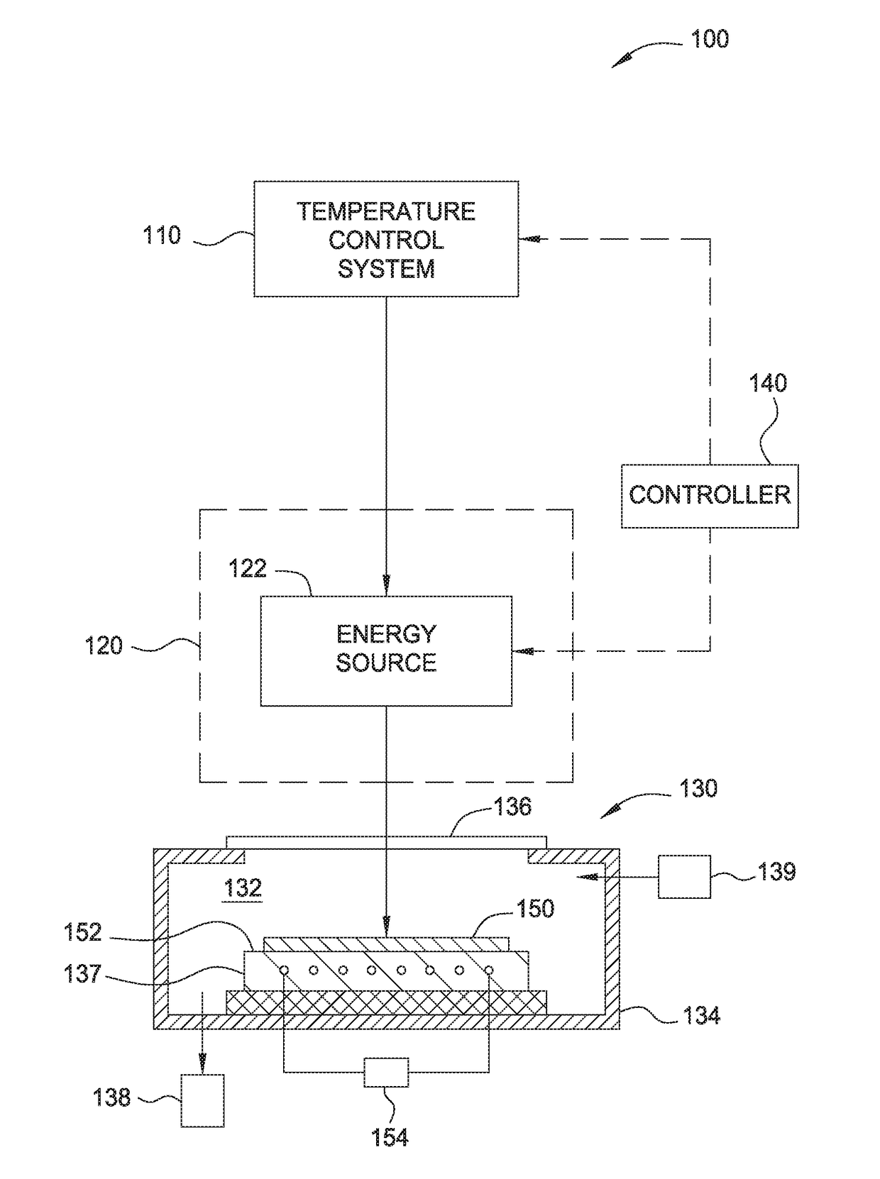
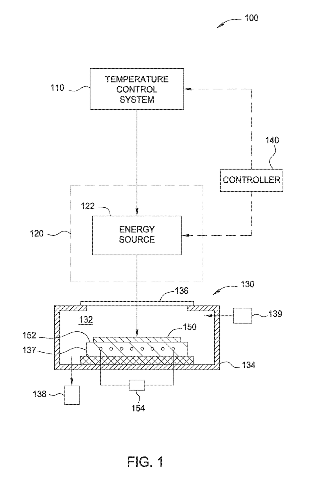
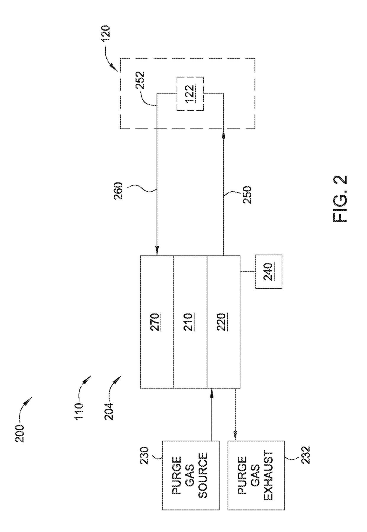
[0016]The following disclosure describes methods and compositions for temperature control of substrate processing equipment. Certain details are set forth in the following description and in FIGS. 1 to 4 to provide a thorough understanding of various implementations of the disclosure. Other details describing well-known structures and systems often associated with temperature control and thermal processing are not set forth in the following disclosure to avoid unnecessarily obscuring the description of the various implementations.

[0017]Many of the details, dimensions, angles and other features shown in the Figures are merely illustrative of particular implementations. Accordingly, other implementations can have other details, components, dimensions, angles and features without departing from the spirit or scope of the present disclosure. In addition, further implementations of the disclosure can be practiced without several of the details described below.

[0018]Implementations descri...


PUM

PropertyMeasurementUnit
temperaturesaaaaaaaaaa
pHaaaaaaaaaa
conductivityaaaaaaaaaa

Abstract

Implementations described herein generally relate to substrate processing equipment and more particularly to methods and compositions for temperature control of substrate processing equipment. In one implementation, a method of cooling a processing chamber component is provided. The method comprises introducing an inert purge gas into a supply reservoir containing a coolant and flowing the treated coolant to a processing chamber component to cool the processing chamber component. The coolant initially comprises deionized water and a water-soluble base.

Description

CROSS-REFERENCE TO RELATED APPLICATIONS[0001]This application claims benefit of U.S. provisional patent application Ser. No. 62 / 327,228, filed Apr. 25, 2016. The aforementioned related patent application is herein incorporated by reference in its entirety.BACKGROUNDField[0002]Implementations described herein generally relate to substrate processing equipment and more particularly to methods and compositions for temperature control of substrate processing equipment.Description of the Related Art[0003]Several applications that involve thermal processing of substrates such as semiconductor wafers and other materials involve the process of rapidly heating and cooling a substrate. Examples of such processing include rapid thermal processing (RTP), physical vapor deposition (PVD), dynamic surface annealing (DSA) and the like, which are used for a number of semiconductor fabrication processes. These processes are often thermally based and typically involve high process temperatures ranging...

Claims


Application Information

Patent Timeline
Patent Type & Authority Applications(United States)
IPC IPC(8): F28F19/00H01L21/67F28F23/00
CPCF28F19/00H01L21/67098F28F23/00C09K5/10H01L21/67109H01L21/67253
Inventor WANG, JIANQILEE, JOUNG WOOPHAM, GIAGERRARD, ALEXMCINTOSH, ROBERT C.
Owner APPLIED MATERIALS INC
Why Eureka
Try Eureka