Particle characterization

a particle and particle technology, applied in the field of particle characterization, can solve the problems of degrading the technique, affecting and the inability to simply expand the size of the detection beam, so as to facilitate the improvement of the optimisation of measurement parameters and improve the signal-to-noise ratio

Active Publication Date: 2017-10-26
MALVERN INSTRUMENTS
View PDF11 Cites 17 Cited by
  • Summary
  • Abstract
  • Description
  • Claims
  • Application Information

AI Technical Summary

Benefits of technology

[0046]In some embodiments, the ability to adjust the volume of the detection region allows the measurement parameters of the particle characterisation process to be better optimized to the properties of the sample, thereby improving signal to noise ratio for samples with high and / or low particle concentrations. Adjustment of both the location and volume of the detection region facilitates improved optimisation of the measurement parameters, and enables significant improvements in the lowest and / or highest concentration of particles that can reliably be characterized.
[0047]The optical arrangement for varying the volume of the detection region may be operable to vary the light beam width incident on the focussing lens.

Problems solved by technology

At high concentrations multiple scattering tends to degrade the technique.
Whilst the static scattering contribution from the wall may be negligible compared with the scattering contribution from particles in a high concentration sample, such static scattering from the wall may be a source of uncorrelated noise (or even static reference signal), for low concentration samples.
However, it may not be practical to simply expand the size of the detection beam to accommodate more particles, because this may increase the size of the beam out of a single coherence area.
Simply increasing the size of the detection optical path may result in non-optimal coupling into such a fibre or may collect light from more than one coherence area, which may reduce the signal to noise ratio.

Method used


Image

  • Particle characterization
  • Particle characterization
  • Particle characterization

Examples


Embodiment Construction

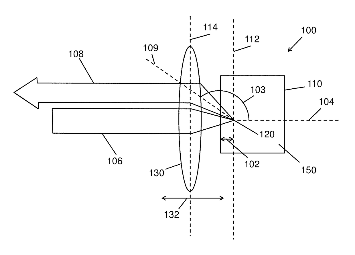
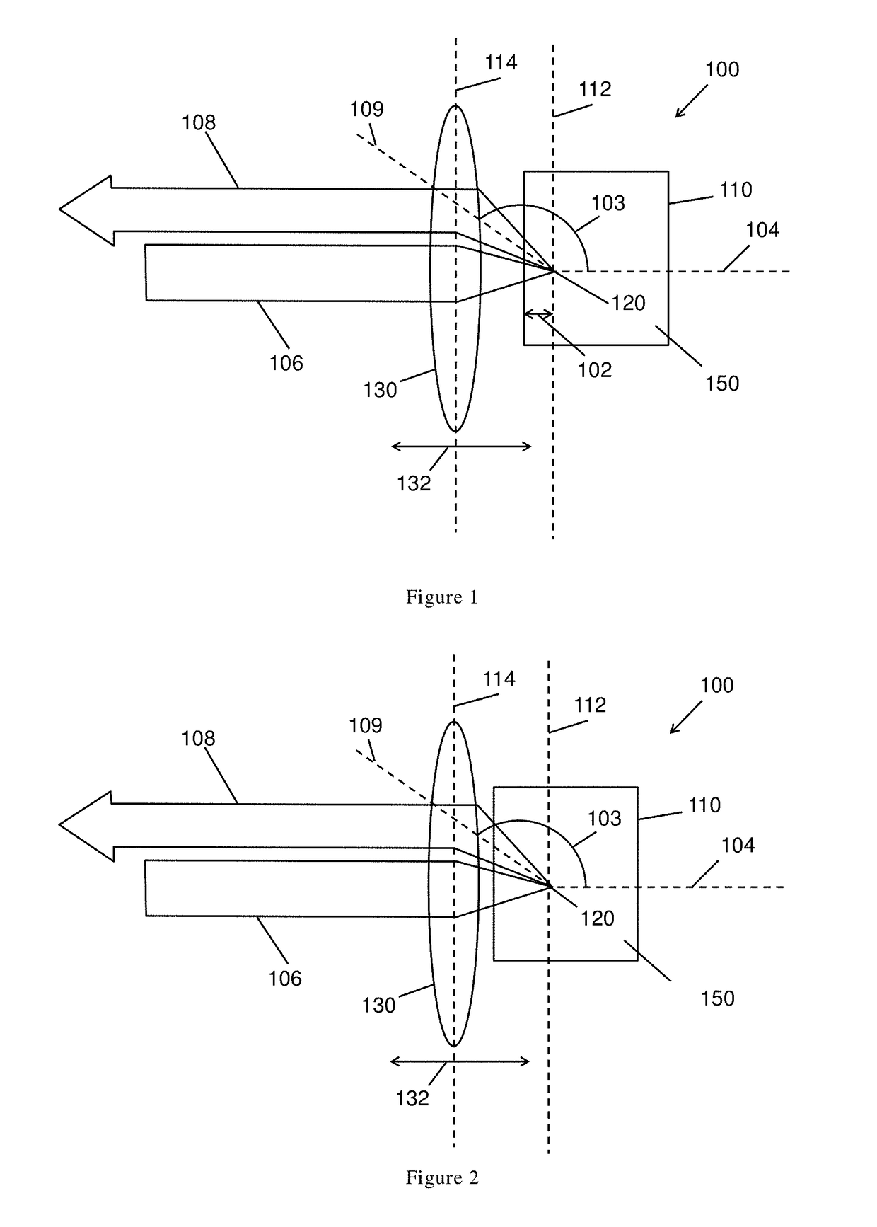
[0114]Referring to FIGS. 1 and 2, a prior art NIBS arrangement 100 is shown, in which an illumination beam 106 is focussed on a sample 150 within a sample cell 110 by a focussing lens 130.

[0115]A detection optical path 108 receives light scattered from the illumination beam 106 by particles dispersed within the sample 150. The detection optical path 108 defines the field of view of a detector (not shown) for detecting the scattered light. The detection optical path 108 may receive light scattered at a narrow range of angles, centred on a specific scattering angle 103 along detection axis 109. The detection optical path 108 is also focussed within the sample 150 by the focussing lens 130.

[0116]The intersection of the illumination beam 106 and the detection optical path 108 define a detection region 120. The position of the detection region 120 within the sample cell 110 can be varied by moving the focussing lens 130, which varies the position of a focal plane 112 of the focussing len...


PUM

PropertyMeasurementUnit
angleaaaaaaaaaa
angleaaaaaaaaaa
angleaaaaaaaaaa

Abstract

A particle characterization apparatus comprising: a light source for illuminating a sample with a light beam; a detector arranged to detect scattered light from the interaction of the light beam with the sample; and a focus tuneable lens arranged to collect the scattered light for the detector from a scattering volume and/or to direct the light beam into the sample.

Description

CROSS-REFERENCE TO RELATED APPLICATIONS[0001]This application claims priority to Great Britain Patent Application No. 1606918.9, filed on Apr. 21, 2016, the contents of which prior application is incorporated herein by reference.FIELD OF THE INVENTION[0002]The present invention relates to a method and apparatus for particle characterization.BACKGROUND OF THE INVENTION[0003]Photon correlation spectroscopy (or dynamic light scattering, DLS) measures the time resolved signal scattered from particle suspensions. The relaxation time of the sample is determined using the correlation function of the scattered signal, from which the particle size distribution can be estimated. The technique works best when each particle in suspension scatters light from the illuminating light beam (e.g. laser) only and not light that has already been scattered from other particles. At high concentrations multiple scattering tends to degrade the technique.[0004]Within a small range of backscattered angles, m...

Claims


Application Information

Patent Timeline
Patent Type & Authority Applications(United States)
IPC IPC(8): G01N15/02G02B7/10G01N15/00
CPCG01N15/0211G01N2015/03G01N2015/0222G02B7/10G01N15/06G01N21/51G01N27/447G01N2015/0693G01N2015/0046G01N27/44721G01N2021/4728
Inventor CORBETT, JASON CECIL WILLIAMBRYCE, DAVID
Owner MALVERN INSTRUMENTS
Why Eureka
Try Eureka