Multicavity Battery Module

a battery module and multi-cavity technology, applied in the field of battery modules, can solve the problems of increased cost, complexity and cost of battery packs, increased cost, etc., and achieve the effects of reducing battery pack complexity, volume and cost, and improving cell cooling

Active Publication Date: 2017-10-26
ROBERT BOSCH GMBH +1
View PDF3 Cites 3 Cited by
  • Summary
  • Abstract
  • Description
  • Claims
  • Application Information

AI Technical Summary

Benefits of technology

[0010]Because the cell has a single-layer electrode assembly with the terminals disposed at one end thereof, and because the cells are very thin, when the cells are stacked within the module, the cell terminals are very closely arranged. The close arrangement of cell terminals eliminates the need for lame and complex high current electrical connection networks that join individual cells. In addition, the cell terminal configuration also allows for a directly connected battery management system (BMS), which further reduces battery pack complexity, volume and cost.
[0011]In some aspects, the battery module is formed of a flexible metal foil laminate material and includes several cavities. In addition, the cells disposed in the cavities include the electrode assembly with the cell housing omitted. For example, the electrode assembly is disposed within the module cavity along with an electrolyte to form an energy storage unit within the cavity. The pouch-type battery module including cell housing-free cells is advantageous when compared to other embodiments in which the cell, including a cell housing and an electrode assembly disposed in the cell housing, is disposed in a cavity of the battery module. In particular, much less metal foil laminate material is required when housing free cells are disposed in the cavities, and cell cooling is also improved. This is because the walls of the module serve as both module housing walls and cell housing walls, and only one layer of metal foil laminate material separates the electrode assemblies of adjacent cells. In contrast, there are three layers of metal foil laminate material separating the electrode assemblies of adjacent cells when the cell includes a cell housing. The additional material layers not only result in additional cost, but also provide increased barriers to heat flow out of the cell and add to overall module thickness and mass.

Problems solved by technology

Although battery packs are used in fully electric vehicles and HEVs, challenges remain for improving the energy density, and reducing mass, complexity and costs of the battery packs.
In addition, it remains difficult to integrate battery packs into existing internal combustion engine vehicle designs.
The additional material layers not only result in additional cost, but also provide increased barriers to heat flow out of the cell and add to overall module thickness and mass.

Method used


Image

  • Multicavity Battery Module
  • Multicavity Battery Module
  • Multicavity Battery Module

Examples


Embodiment Construction

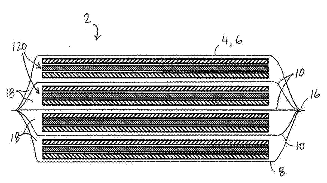
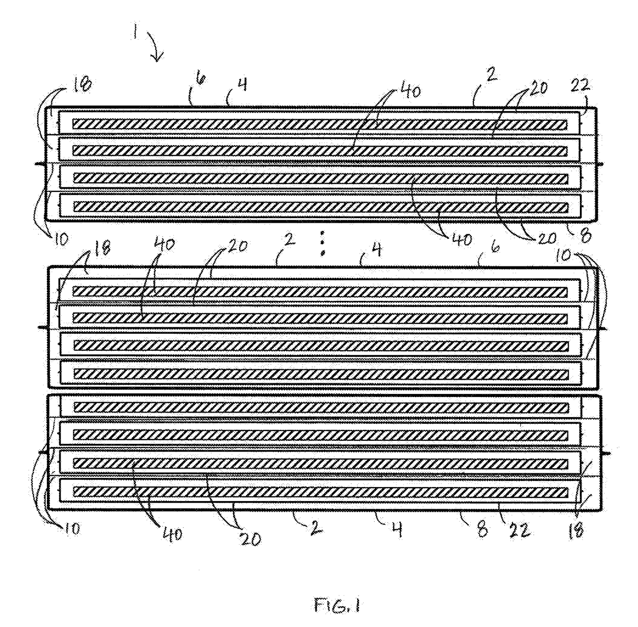
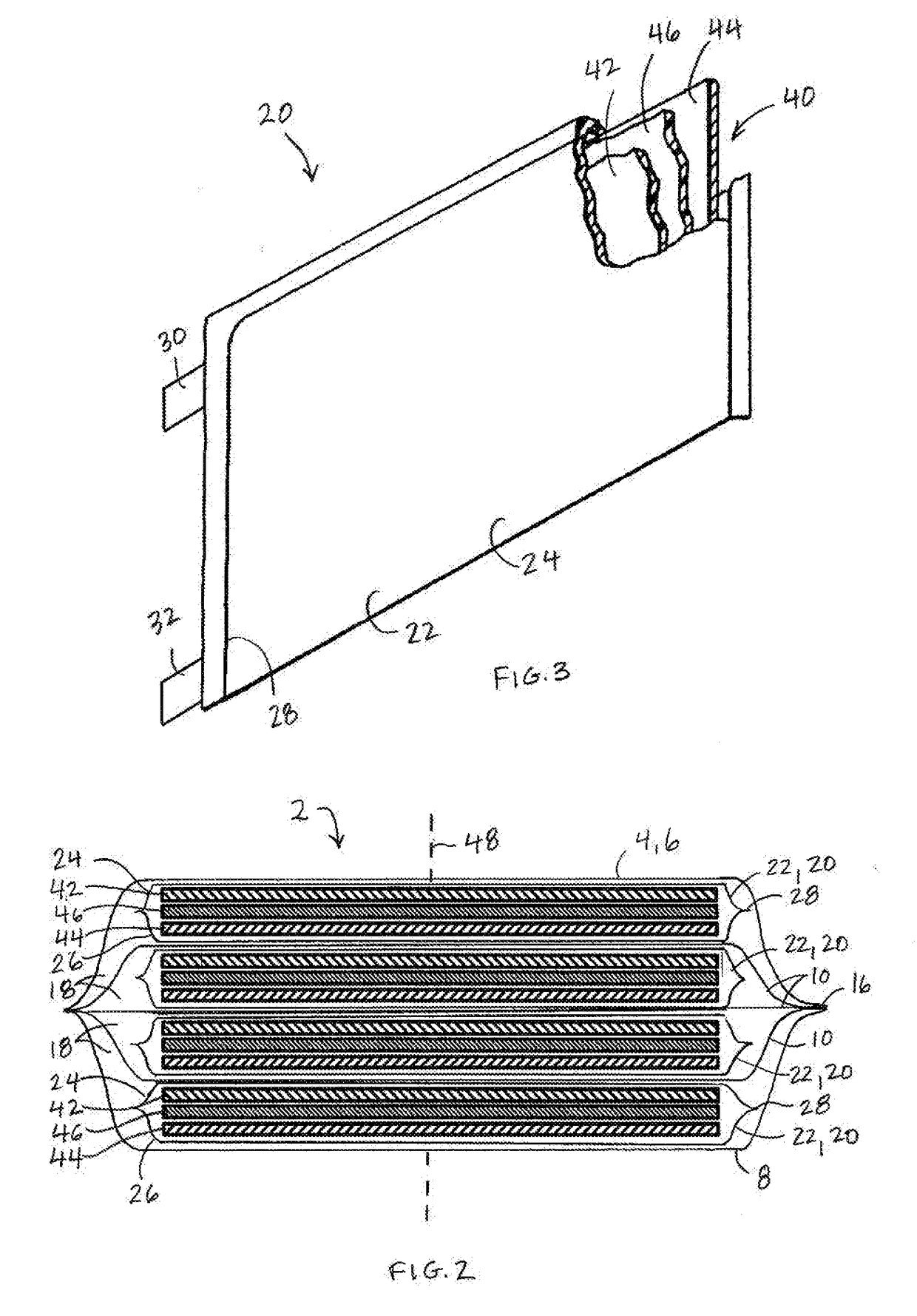
[0022]Referring to FIGS. 1-2, a battery pack 1 used to provide electrical power includes electrochemical cells 20. The cells 20 are very thin, large-area lithium-ion pouch cells that include a single-layer electrode assembly 40 that is sealed within a cell housing 22 along with an electrolyte to form an energy storage unit. Cells 20 are electrically interconnected and stored in an organized manner within a module housing 4 to form a battery module 2. The module housing 4 is segregated into a plurality of cavities 18. Each cavity 18 is configured to receive a single cell 20. Within the battery module 2, the cells 20 are electrically connected in series or in parallel, and within the battery pack 1, the battery modules 2 are electrically connected in series or in parallel. The resulting battery pack 1 is relatively thin, has a large area, and can be provided in any desired profile including complex, curved geometries, allowing for space efficient integration into a vehicle body, as di...


PUM

PropertyMeasurementUnit
widthaaaaaaaaaa
thicknessaaaaaaaaaa
thicknessaaaaaaaaaa

Abstract

A battery module includes a battery module housing that defines an interior space. The battery module housing includes at least one interior wall that segregates the interior space into at least two cavities. The battery module housing and the at least one interior wall are formed of a flexible laminate material, and an electrochemical cell is disposed in one of the at least two cavities. The cell may include a housing formed of a flexible laminate material, or alternatively may be housing-free.

Description

BACKGROUND1. Field of the Invention[0001]The present disclosure relates to a battery module that includes a battery module housing that is segregated into individual cavities, and each cavity is configured to receive a single electrode cell.2. Description of the Related Art[0002]Battery packs provide power for various technologies ranging from portable electronics to renewable power systems and environmentally friendly vehicles. For example, hybrid electric vehicles (HEV) use a battery pack and an electric motor in conjunction with a combustion engine to increase fuel efficiency. Battery packs are formed of a plurality of battery modules, where each battery module includes several electrochemical cells. The cells may be arranged in two or three dimensional arrays and are electrically connected in series or in parallel. Likewise, the battery modules within a battery pack are electrically connected in series or in parallel.[0003]Different cell types have emerged in order to deal with ...

Claims


Application Information

Patent Timeline
Patent Type & Authority Applications(United States)
IPC IPC(8): H01M2/02H01M10/0525H01M50/119H01M50/128H01M50/211H01M50/224H01M50/231H01M50/55H01M50/557
CPCH01M2/0267H01M10/0525H01M2/0287H01M2/0262Y02E60/10H01M50/557H01M50/124Y02P70/50H01M50/224H01M50/231H01M50/55H01M50/211H01M50/128H01M50/119H01M10/0413H01M10/0436H01M10/0585H01M50/105
Inventor MILLON, CHRISTOPHER
Owner ROBERT BOSCH GMBH
Why Eureka
Try Eureka