Slicing machine and method for slicing elastic strands in particular meat strands

a technology of elastic strands and cutting machines, which is applied in the field of cutting elastic strands, can solve the problems of high level of automation and long idle times, and achieve the effects of short idle times, high throughput, and production of weight-precise slices and portions

Active Publication Date: 2017-11-02
TVI ENTWICKLUNG & PROD GMBH
View PDF0 Cites 17 Cited by
  • Summary
  • Abstract
  • Description
  • Claims
  • Application Information

AI Technical Summary

Benefits of technology

[0014]Thus it is an object of the invention to provide a cutting machine and a cutting method which facilitates short idle times and, as a result, a high through put while be able to produce weight-precise slices and portions.

Problems solved by technology

This causes rather long idle times between the cutting phases and has required hand loading to this date.
It is disadvantageous that an employee for loading one to three cutting machines is required for this purpose, or a high level of automation is required in order not to need this employee.

Method used


Image

  • Slicing machine and method for slicing elastic strands in particular meat strands
  • Slicing machine and method for slicing elastic strands in particular meat strands
  • Slicing machine and method for slicing elastic strands in particular meat strands

Examples


first embodiment

[0183]The side view of FIGS. 4A, 4B, and 4C of a cutting unit shows, in particular FIG. 4A that the stop plate 13 is adjustable for this purpose in the axial direction 10a and / or in the first transversal direction relative to the blade 3. The blade plane 3′ is defined by a contact surface of the blade 3 that is oriented towards the cutting material, wherein a cutting edge 3a of the blade 3 is in the blade plane 3′ when the blade 3 is only ground at a side that is oriented away from the contact surface.

[0184]When the blade 3 is moved for cutting off a slice 101 from its starting position according to FIG. 4A in the first blade transversal direction 31.1, the second transversal direction 11.2 of the machine, in a cutting movement 28a in a downward slanted direction over the free inner cross section 7′ of the two form tubes 2. The stop plate 13 which is combined with the blade 3 in a cutting unit 27 moves together with the blade 3 in the first blade transversal direction 31.1, here in ...

second embodiment

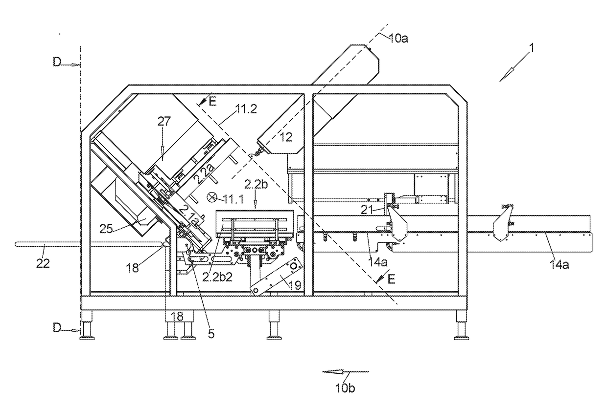
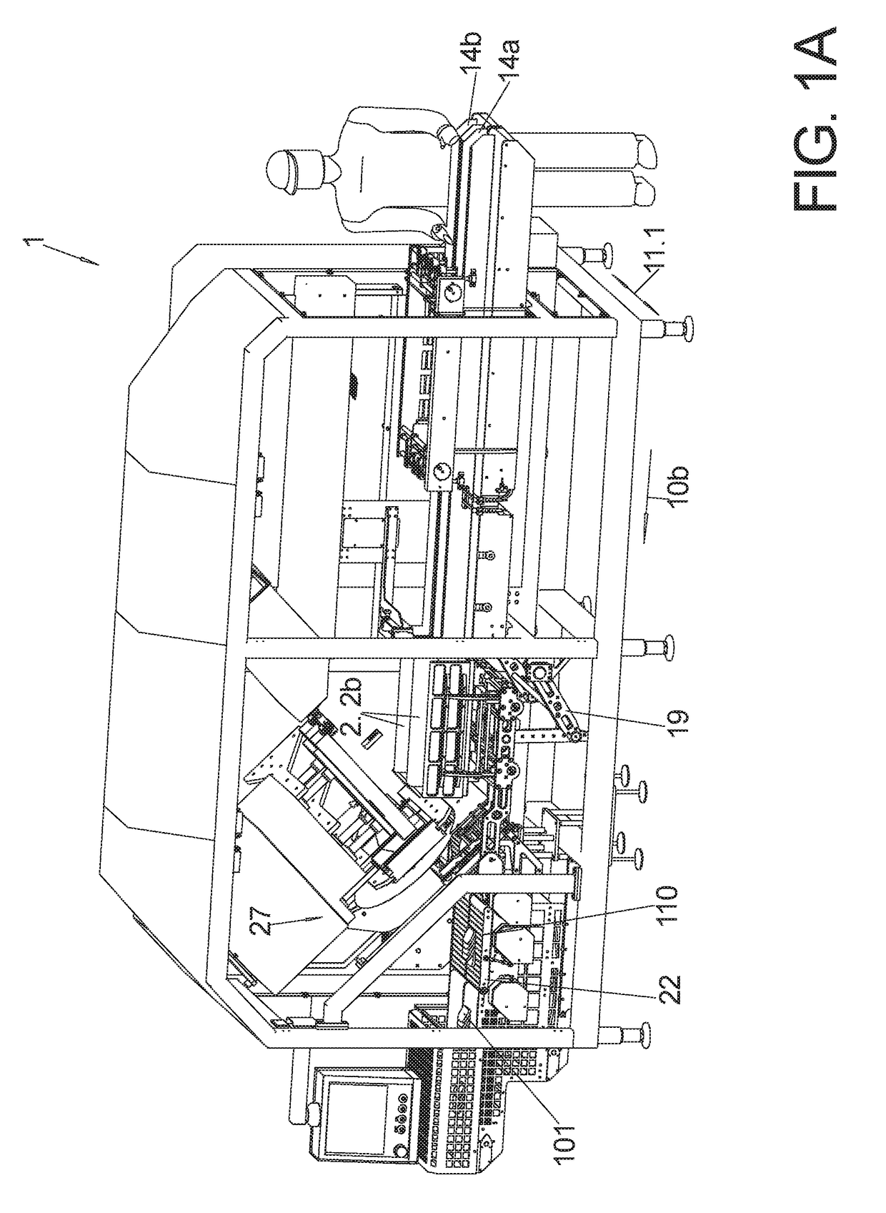
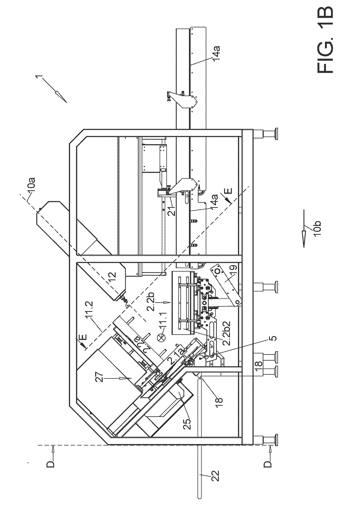
[0255]the cutting machine 1 that differs from FIGS. 1-5 is illustrated in FIGS. 6A, 6B with the two form tubes 2 arranged adjacent to each other in FIG. 6A in the loading position and in FIG. 6B in the slicing positon. Also this embodiment can simultaneously process two respective meat strands 100 onto adjacent tracks.

[0256]The second embodiment differs from the embodiment of FIGS. 1-5 as follows:

[0257]In order to perform approaching and off-setting the rear U-shaped components 2.2b relative to the rear transversal press plunger 2.2a or the transversal press plunger 2.1+2.a extending over an entire axial length of the form tubes are moved apart or together. In the first transversal direction 11.1, wherein the two components keep their parallel alignment relative to each other in that in turn using the scissor rod arrangement, 19 the rear U-shaped component 2.2b is offset from a remainder of the form tube 2, not by pivoting about a pivot axis.

[0258]Thus each rear U-shaped component 2...


PUM


Abstract

A slicing machine for slicing meat strands that have a cross section that varies over a longitudinal extension in large numbers and as quickly as possible into weight precise slices. In one embodiment, two meat strands are received adjacent to each other in a respective form tube and pushed against a respective separately adjustable stop plate independently from each other by a controlled longitudinal press plunger and compressed in the longitudinal direction. In addition, a cross section of the form tubes may be reduced in a first transversal direction jointly and in a second transversal direction independently from each other and thus the respective meat strand is transversally compressed to a constant cross section prior to slicing.

Description

CROSS-REFERENCE TO RELATED APPLICATIONS[0001]This Application claims priority to German Patent Application Number 102016107849.2 filed Apr. 28, 2016, to Thomas Volkl and Martin Mayr, currently pending, the entire disclosure of which is incorporated herein by reference.FIELD OF THE INVENTION[0002]The invention relates to slicing an elastic strand like e.g. a meat strand into weight precise slices.BACKGROUND OF THE INVENTION[0003]Producing weight precise slices or portions from an elastic strand material is rather simple when the strand material has an identical cross section over its entire length and it is made from a homogenous material that can be cut everywhere with the same ease, like e.g. sausage or cheese.[0004]For this purpose so called slicers are known which cut off a respective slice with a typically circular or spiral shaped rotating blade which can be moved back and forth respectively transversal to the strand, whereas the typically exposed strand is moved forward contin...

Claims


Application Information

Patent Timeline
Patent Type & Authority Applications(United States)
IPC IPC(8): B26D7/30A22C17/00B26D7/06B26D5/30
CPCB26D7/30A22C17/002B26D7/0641B26D7/0683B26D2210/02B26D7/0625B26D5/30B26D1/143B26D7/0608B26D7/08B26D7/1818A22C25/08A22C25/18B26D3/16B26D5/02B26D5/06B26D5/08B26D5/086B26D2007/013B26D2210/04A22C17/0033B26D7/01A22C17/02A22C25/10
Inventor VOLKL, THOMASMAYR, MARTIN
Owner TVI ENTWICKLUNG & PROD GMBH
Why Eureka
Try Eureka