Climbing Robot Vehicle

a robot vehicle and robot technology, applied in the field of climbing robot vehicles, can solve the problems of limiting its application, and achieve the effects of reducing pressure, reducing disturbance flow, and maximally inhibiting impa

Active Publication Date: 2017-11-02
ZHEJIANG UNIV
View PDF0 Cites 18 Cited by
  • Summary
  • Abstract
  • Description
  • Claims
  • Application Information

AI Technical Summary

Benefits of technology

[0017]1. The first exhaust duct is provided to eliminate the local high pressure distribution which the lower surface of the cover plate forms, thereby ensuring that a pressure is applied to the vehicle. When the climbing robot vehicle clings to a vertical wall, the pressure generates a friction force between the vehicle and the wall. The friction force not only overcomes the gravity of the vehicle itself, but also provides a driving force required for moving the vehicle.
[0018]2. The second exhaust duct is provided to avoid contact between the lower end face of the hollow cylinder and the wall, so the vehicle can travel smoothly on the wall.
[0020]4. A soft pad is provided to block the exhaust flow of the second exhaust duct between the wall and the hollow cylinder, thus eliminating the disturbance flow caused by concavity, convexity and unevenness of the wall in the second exhaust duct, maximally inhibited the impact which concave, convex and unevenness of the wall have on the pressure distribution; the soft pad also blocks the air entering the airflow in the hollow cylinder from the outside reflux, maximally protecting the rotation flow in the hollow cylinder.
[0021]5. The third exhaust duct is provided to reduce the pressure on the part between the annular baffle and the wall and beyond the soft pad, thereby increasing the pressure which the robot vehicle bears.

Problems solved by technology

However, the drawback is that the wall the robot climbs must have a magnetic field in order to generate a suction force, which greatly limits its application.

Method used


Image

  • Climbing Robot Vehicle
  • Climbing Robot Vehicle
  • Climbing Robot Vehicle

Examples


embodiment 1

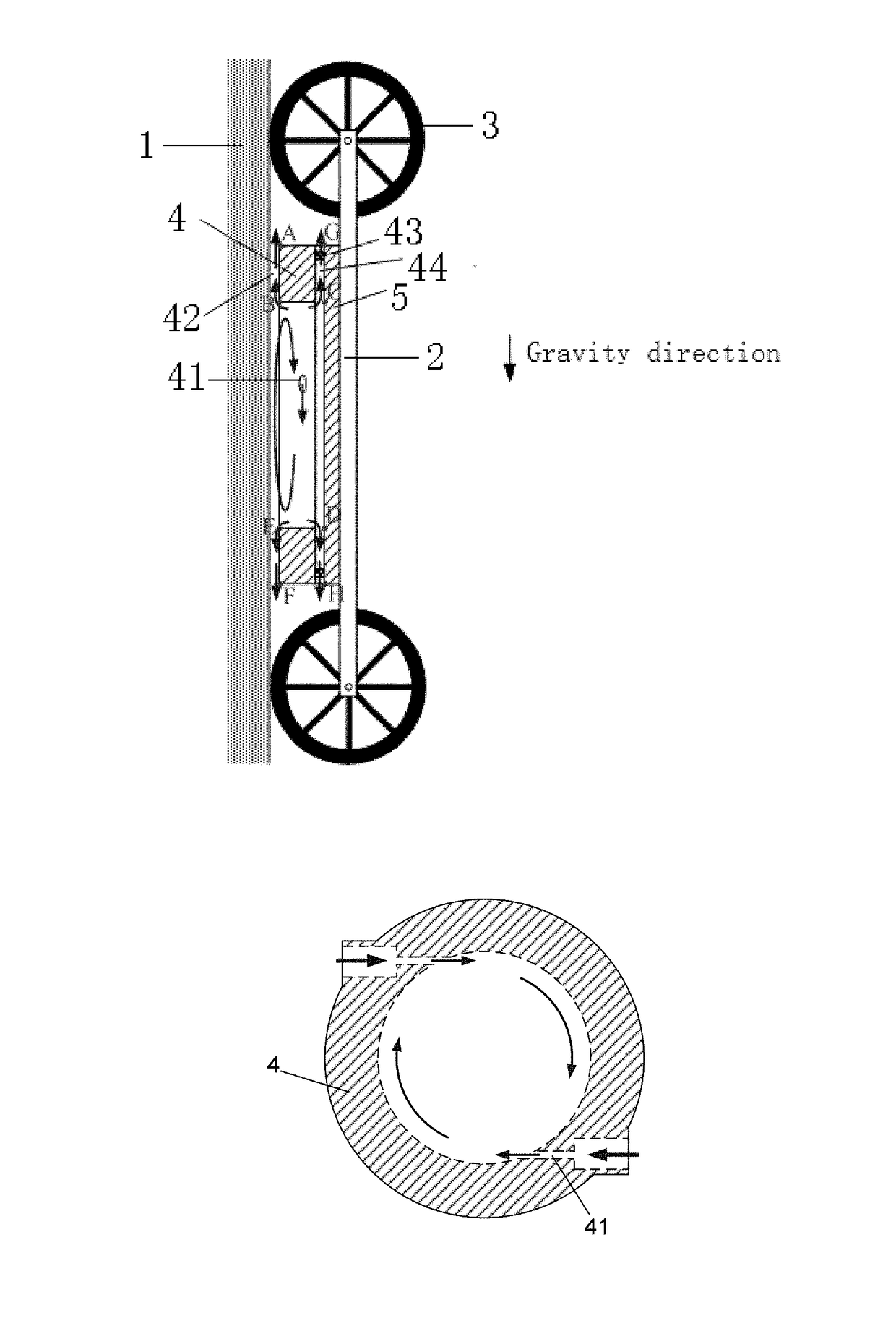
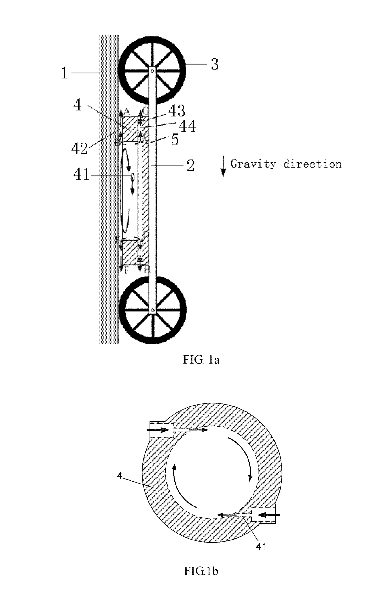
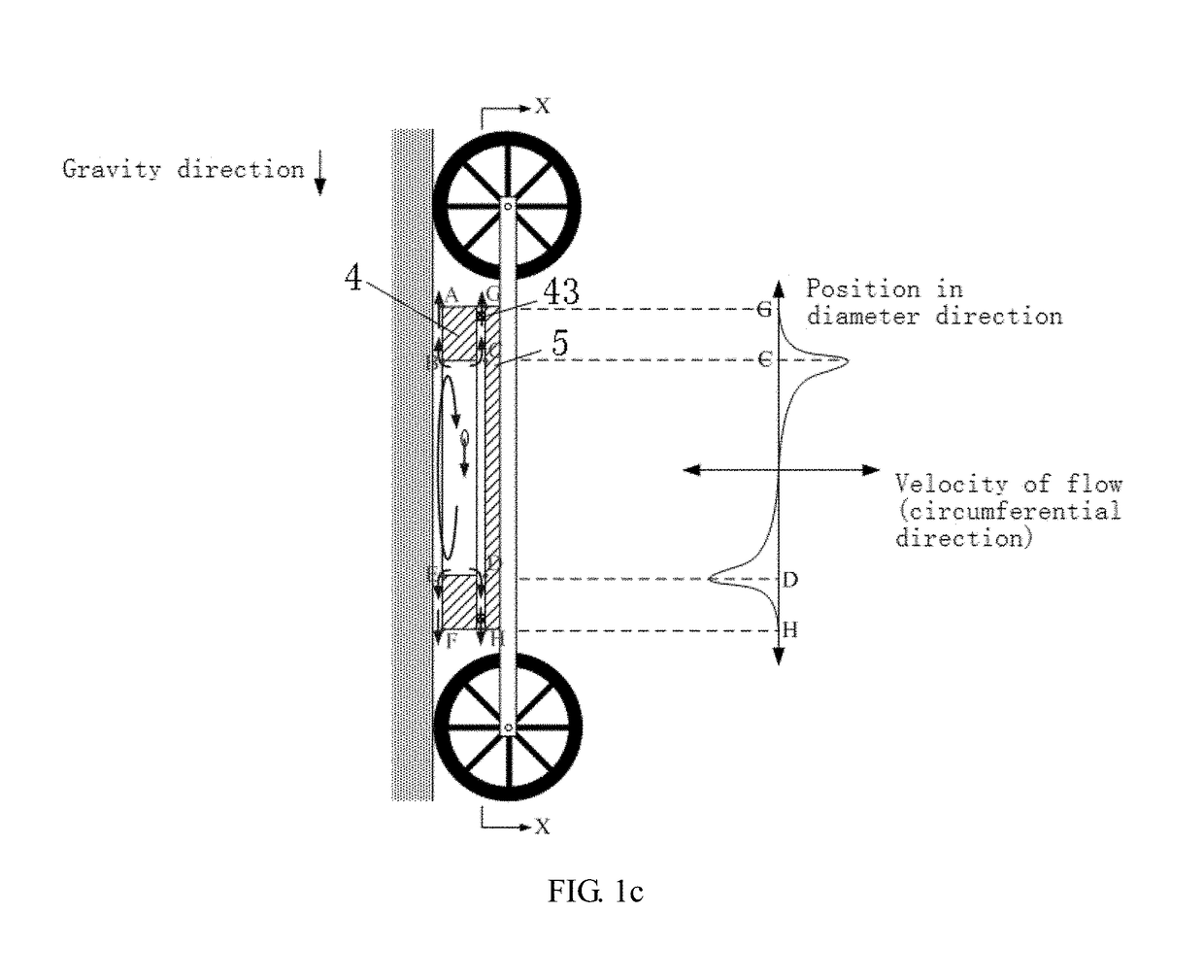
[0036]Climbing robot vehicle according to FIG. 1a, FIG. 1b and FIG. 1c, comprises a vehicle 2 and the front and rear ends of the vehicle 2 are provided with wheels 3. The end of the vehicle 2 facing towards the wall 1 is fixedly connected with a sucking mechanism. The sucking mechanism comprises a body, wherein the body being a hollow cylinder 4. A cover plate 5 is provided above the hollow cylinder 4. The inner wall of the hollow cylinder 4 is provided with tangential nozzles 41. The upper end face of the cover plate 5 is fixedly connected with the vehicle 2 and the lower end face of the cover plate 5 is fixedly connected with the outer edge of the upper end face of the hollow cylinder 4 by means of the first blocks 43 spaced from each other. The space between the first blocks 43 forms a first exhaust duct 44 between the outer edge of the upper end face of the hollow cylinder and the lower end face of the cover plate. A gap is formed between the lower end face of the hollow cylinde...

embodiment 2

[0043]According to FIG. 4, on the basis of the above embodiment 1, the upper end face of the vehicle 2 is provided with an electric motor 6, while the electric motor 6 is connected with the cover plate 5 by means of the screw 61 it drives; the screw 61 is connected with the screw thread of the cover plate 5; the cover plate 5 is provided with pressure measuring holes which are connected with pressure sensors 7; the cover plate is connected with the hollow cylinder 4 by means of connecting rods 9, while the connecting rods 9 are provided on the outer edge of the upper end face of the hollow cylinder 4; both ends of the connecting rods 9 are processed with a screw, the intermediate section of the connecting rod is a cylinder, and stairs are provided between the cylinder and the screw. Both ends of the screw are fixedly connected with the screw thread of the vehicle and that of the hollow cylinder respectively. The position in the cover plate corresponding to the connecting rod is prov...

embodiment 3

[0048]According to FIG. 5, on the basis of the above embodiment 1, the upper end face of the vehicle 2 is provided with an electric motor 6, while the electric motor 6 is connected with the cover plate 5 by means of the screw 61 it drives; the screw 61 is connected with the screw thread of the cover plate 5; the cover plate 5 and the hollow cylinder 4 are provided with pressure measuring holes, and the pressure measuring holes are connected with pressure sensors 7. The vehicle 2 is provided with guide holes. The inside of each of guide hole is provided with a guide column 8. One end of the guide column 8 is fixedly connected to the upper end face of the cover plate 5 through the guide hole. The guide column 8 can slide in the guide hole.

[0049]In this embodiment, after rotating in the hollow cylinder, a part of the air is discharged through the first exhaust duct, and the other part is discharged through the second exhaust duct. This embodiment is a further improvement scheme of the ...


PUM


Abstract

A climbing robot vehicle comprises a vehicle (2) and the front and rear ends of the vehicle body are provided with wheels (3). The end of the vehicle body facing towards the wall is fixedly connected to a sucking mechanism. The sucking mechanism comprises a body, the body being a hollow cylinder (4). A cover plate (5) is provided above the hollow cylinder. The upper end face of the cover plate is fixedly connected with the vehicle body and the lower end face of the cover plate is fixedly connected with the outer edge of the upper end face of the hollow cylinder by means of the first blocks (43) spaced from each other. The inner wall of the hollow cylinder is provided with tangential nozzles (41). The space between the first blocks (43) forms a first exhaust duct (44) between the outer edge of the upper end face of the hollow cylinder and the lower end face of the cover. A gap is formed between the lower end face of the hollow cylinder and the wall, and the gap forms a second exhaust duct (42) between the outer edge of the lower end face of the hollow cylinder and the wall. The climbing robot vehicle can be sucked on various kinds of walls and has a strong sucking ability and a wide application range.

Description

BACKGROUND OF THE INVENTION[0001]The invention is related to a climbing robot vehicle.[0002]A climbing robot vehicle is able to walk on the vertical walls and ceilings, and in many specific occasions plays an important role. For example, we install ultrasonic flaw detector on the vehicle, then the climbing robot vehicle can replace people to carry out flaw detection of large-scale buildings (bridges, tunnels, etc.), greatly reducing the operation cost and shortening the working hours.[0003]In order to make the climbing robot vehicle clinging to the wall, we need to apply a pressure pointing to the wall on the vehicle. When the climbing robot vehicle clings to a vertical wall, the pressure generates a friction force between the vehicle and the wall. The friction force not only overcomes the gravity of the vehicle itself, but also provides a driving force required for moving the vehicle; when the climbing robot vehicle clings to the ceiling wall, a part of the pressure directly overco...

Claims


Application Information

Patent Timeline
Patent Type & Authority Applications(United States)
IPC IPC(8): B62D57/024B62D57/04B25J15/06
CPCB62D57/04B25J15/06B62D57/024G01N29/225G01N29/265
Inventor LI, XIN
Owner ZHEJIANG UNIV
Why Eureka
Try Eureka