Radiation heating device

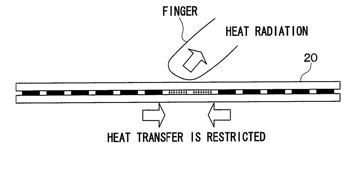
a heating device and radiation technology, applied in the field of radiation heating devices, can solve the problems of user's thermal unconformity, the surface temperature of the heat radiation portion gradually rises, etc., and achieve the effects of reducing heat conductivity, reducing heat transfer, and reducing the temperature of the contact site with the obj

Active Publication Date: 2017-11-09
DENSO CORP
View PDF5 Cites 4 Cited by
  • Summary
  • Abstract
  • Description
  • Claims
  • Application Information

AI Technical Summary

Benefits of technology

[0009]With such a configuration, the plurality of heat radiation portions that radiate heat transferred from the heat generation portion are disposed in the heat generation layer, and a low heat conduction portion having a lower heat conductivity than the heat radiation portions is provided around each of the heat radiation portions. Thus, when an object contacts the surface of the heat generation layer, heat of the heat radiation portion located close to a contact site of the heat generation layer with the object is radiated to the object, and the low heat conduction portion that encloses the heat radiation portion suppresses heat transfer to the heat radiation portion. As a result, the temperature of the contact site with the object can be rapidly lowered. When contact of the object with the heat generation layer is detected, the energization amount of the heat generation portion is decreased. For this reason, even when the contact with the object continues for a long time, an increase in the temperature of the heat generation layer is suppressed. This can suppress the temperature of the heat generation layer from increasing when the human body contacts the heat generation layer, thereby reducing thermal discomfort of the human body.

Problems solved by technology

However, even in such a case, the heat generation portions remain energized, and the temperature of the surfaces of the heat radiation portions gradually rises.
Accordingly, when the human body continuously contacts the heat radiation portion for a long time, the user feels thermally unconformable.

Method used


Image

  • Radiation heating device
  • Radiation heating device
  • Radiation heating device

Examples


first embodiment

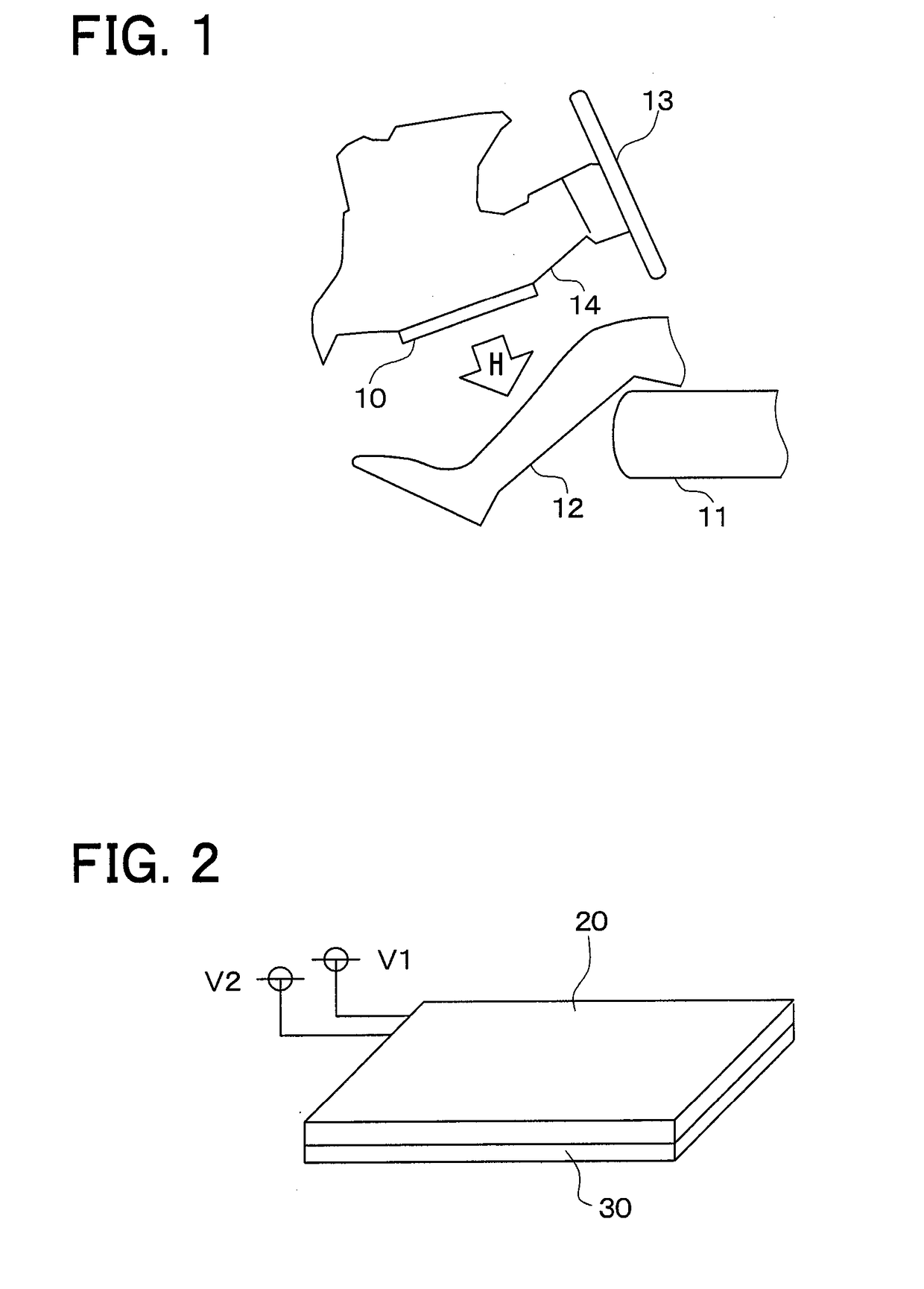
[0044]The first embodiment will be described below with reference to FIG. 1 to FIG. 8. As illustrated in FIG. 1, a radiation heating device 10 in the first embodiment is installed in the interior of a vehicle travelling on a road. The heater device 10 constitutes a part of an indoor heating system. The heater device 10 is an electric heater that receives power from a power source such as a battery and a generator in the vehicle to generate heat. The heater device 10 is formed into a thin plate. In order to heat an object located vertical to the surface of the heater device 10, the heater device 10 radiates radiant heat H mainly in the direction vertical to the surface.

[0045]A seat 11 on which a passenger 12 sits is installed in the interior of the vehicle. The heater device 10 is disposed in the interior to radiate radiant heat H to feet of the passenger 12. The heater device 10 can be used to quickly heat the passenger 12, for example, immediately after activation of another heatin...

second embodiment

[0088]A heater device 10 in the present embodiment has the same configuration as the heater device 10 in the first embodiment. The heater device 10 in the first embodiment lowers the heater control temperature when contact with an object is detected in S100. On the contrary, the heater device 10 in the present embodiment lowers the heater control temperature when contact with the object for a certain time period or more is detected.

[0089]FIG. 12 is a flowchart of the control unit 40 of the heater device 10 in the present embodiment. When the heater device 10 is activated in accordance with the user's operation of the operation unit 50, the control unit 40 determines whether or not contact with the object for a certain time period or more is detected. Here, the certain time period is set to a time elapsed until the user feels thermal discomfort after contact with the heat generation portion 24. Specifically, it is determined whether or not contact with the object for the certain time...

third embodiment

[0092]A heater device 10 in the present embodiment has the same configuration as the heater device 10 in the first embodiment. The control unit 40 of the heater device 10 in the present embodiment determines whether or not local abnormal heat generation of the heater is detected using the resistor 31 that changes in resistance value according to a temperature change, and executes processing of deactivating the heater when the local abnormal heat generation is detected.

[0093]FIG. 13 is a flowchart of the control unit 40 of the heater device 10 in the present embodiment. When the heater device 10 is activated in accordance with the user's operation of a switch of the operation unit 50, the control unit 40 periodically executes processing illustrated in FIG. 13 in addition to the processing illustrated in FIG. 10.

[0094]First, it is determined whether or not local abnormal heat generation caused by any cause of the heater is detected (S300). Specifically, it is determined whether or not...


PUM


Abstract

A radiation heating device includes: a planar heat generation layer; a heat generation portion that is provided in the heat generation layer and that generates heat by energization; a plurality of heat radiation portions that are disposed in the heat generation layer and that radiate heat transferred from the heat generation portion; a low heat conduction portion that is provided around each of the heat radiation portions and that has a lower heat conductivity than the heat radiation portions; and a contact detection unit that detects contact of an object with the heat generation layer. The radiation heating device further includes an energization amount decrease unit that decreases an energization amount of the heat generation portion when the contact detection unit detects the contact of the object with the heat generation layer.

Description

CROSS REFERENCE TO RELATED APPLICATIONS[0001]This application is based on Japanese Patent Application No. 2014-152199 filed on Jul. 25, 2014, Japanese Patent Application No. 2014-223865 filed on Nov. 3, 2014, and Japanese Patent Application No. 2015-41659 filed on Mar. 3, 2015, the disclosures of which are incorporated herein by reference.TECHNICAL FIELD[0002]The present disclosure relates to a radiation heating device.BACKGROUND ART[0003]A conventional heater device includes plural heat radiation portions and plural heat generation portions. The heat generation portion is formed into a thin plate. The plural heat radiation portions are dispersed, and a low heat conduction portion is provided between the two adjacent heat radiation portions.[0004]The low heat conduction portion surrounds the entire periphery of the heat radiation portion, thereby thermally separating the plural heat radiation portions from each other (refer to, for example, Patent Literature 1).PRIOR ART LITERATURES...

Claims


Application Information

Patent Timeline
Patent Type & Authority Applications(United States)
IPC IPC(8): F24C7/04G06F3/041F24D13/02H05B3/20B60H1/22
CPCF24C7/04B60H1/22G06F3/041H05B3/20F24D13/02F24D19/1096H05B6/34H05B2203/02H05B2203/029H05B2203/032B60H1/2215B60H1/2218B60H2001/2228B60H2001/2256B60H2001/2268B60H2001/2287B60H2001/2293Y02B30/00F24C7/043
Inventor ISHIKAWA, KIMITAKEKAKO, HIDEAKIOIDE, HIROYASUSEKI, HIDEKISUMIDA, YOSHINOBUSAGOU, YASUHIRO
Owner DENSO CORP
Why Eureka
Try Eureka