
Selective deposition using hydrophobic precursors

a technology of hydrophobic precursors and selective deposition, which is applied in the direction of coatings, chemical vapor deposition coatings, metallic material coating processes, etc., can solve the problems of loss of selectivity in selective ald processes, undesired cvd growth, and difficult deposition of hsub>2/sub>o

Active Publication Date: 2017-11-09
ASM IP HLDG BV
View PDF11 Cites 60 Cited by
  • Summary
  • Abstract
  • Description
  • Claims
  • Application Information

AI Technical Summary

Benefits of technology

The patent text describes a method for selectively depositing a material on a first surface of a substrate relative to an organic surface. This is achieved by contacting the substrate with a first vapor phase hydrophobic reactant and a second vapor phase reactant. The material can be a metal or metallic material, such as metal oxide or metal nitride, and can be deposited using a chemical vapor deposition process or an atomic layer deposition process. The selectivity of the material deposition can be greater than 50%, 60%, 70%, 80%, 90%, or 95%.

Problems solved by technology

However, H2O can be problematic since it is difficult to completely remove from the reaction chamber during deposition.
This accumulated water may cause CVD growth and can lead to loss of selectivity in selective ALD processes.
Further, if H2O molecules are able to penetrate between the long carbon chains of a self-assembled monolayer (SAM) or inside another organic material, such as polymer material, it is possible that these H2O molecules will be present when a metal precursor is provided and thus undesired CVD growth may occur.
Increasing the purge time to address these issues would increase the overall processing time significantly and at the same time would decrease the throughput.

Method used


Image

  • Selective deposition using hydrophobic precursors
  • Selective deposition using hydrophobic precursors
  • Selective deposition using hydrophobic precursors

Examples


examples

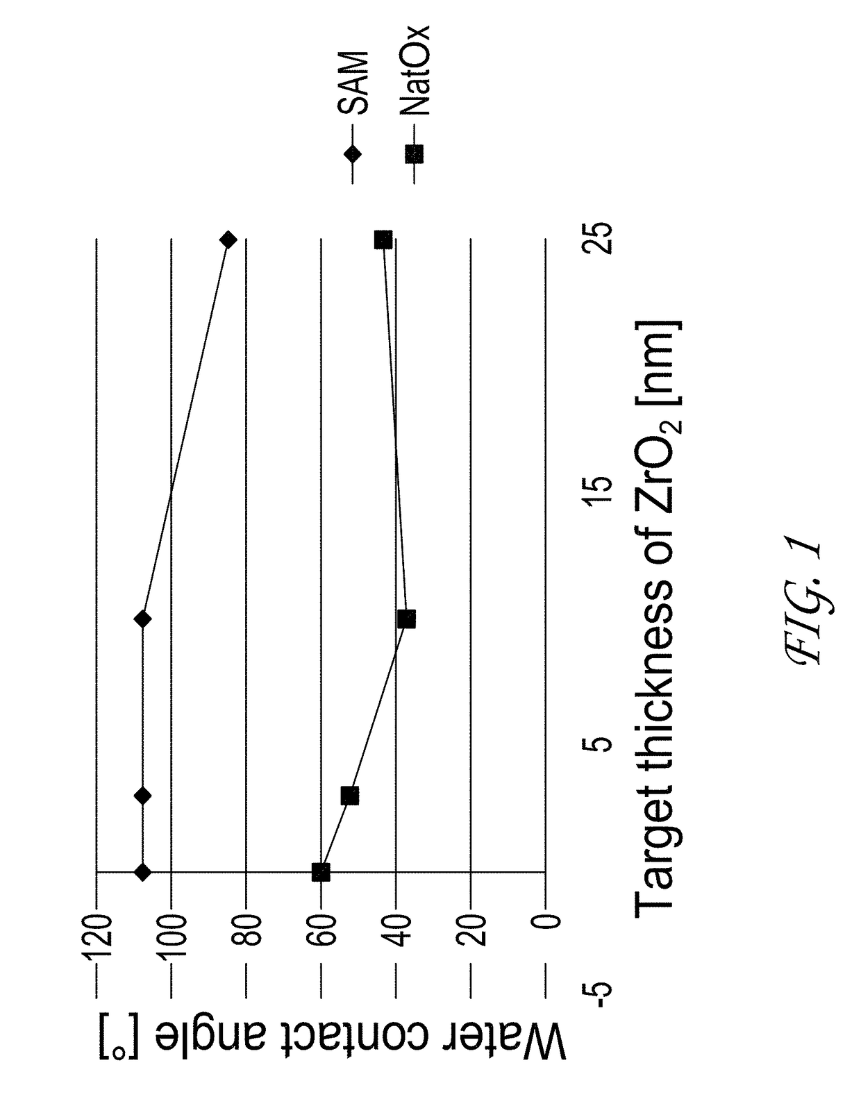
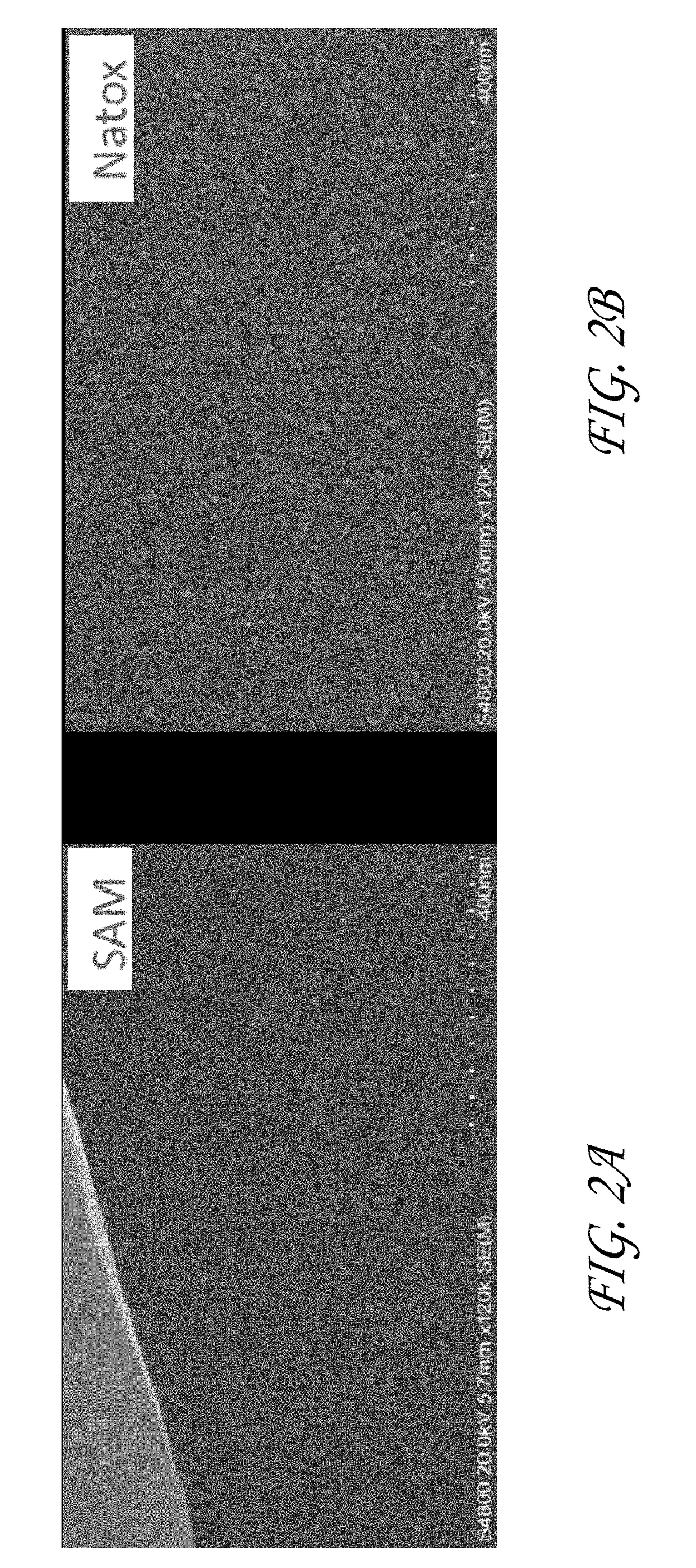
[0121]ZrO2 was deposited by ALD on various substrates and under various reaction conditions in a Pulsar® 2000 reactor. Bis(methylcyclopentadienyl) methoxymethyl Zirconium(IV) and H2O were used as the first hydrophobic reactant and second reactant, respectively. Deposition of ZrO2 was not observed on substrates comprising a surface with a SAM layer (Trichloro(octadecyl)silane) or a polyimide surface. See FIGS. 1-4.

[0122]In the tests on the SAM surface, two coupon substrates, a natox / Si and SAM / natox / Si, were placed into the ALD reactor where the ZrO2 deposition processes were carried out. The contact angle (CA) measurement that indicates the hydrophobic or hydrophilic nature of the surface was used to study the passive nature of the SAM layer on the natox / Si coupon. The contact angle was measured before and after the ZrO2 deposition from both substrates.

[0123]Before ZrO2 deposition the contact angle of the SAM layer was very high (>105° indicating very hydrophobic nature of the surfa...


PUM

PropertyMeasurementUnit
Fractionaaaaaaaaaa
Fractionaaaaaaaaaa
Dielectric polarization enthalpyaaaaaaaaaa

Abstract

Vapor deposition processes are provided in which a material is selectively deposited on a first surface of a substrate relative to a second organic surface. In some embodiments a substrate comprising a first surface, such as a metal, semi-metal or oxidized metal or semi-metal is contacted with a first vapor phase hydrophobic reactant and a second vapor phase reactant such that the material is deposited selectively on the first surface relative to the second organic surface. The second organic surface may comprise, for example, a self-assembled monolayer, a directed self-assembled layer, or a polymer, such as a polyimide, polyamide, polyuria or polystyrene. The material that is deposited may be, for example, a metal or metallic material. In some embodiments the material is a metal oxide, such as ZrO2 or HfO2. In some embodiments the vapor deposition process is a cyclic chemical vapor deposition (CVD) process or an atomic layer deposition (ALD) process. In some embodiments the material is deposited on the first surface relative to the second surface with a selectivity of greater than about 50%, greater than about 60%, greater than about 70%, greater than about 80%, greater than about 90% or greater than about 95%.

Description

REFERENCE TO RELATED APPLICATIONS[0001]The present application claims priority to U.S. Application No. 62 / 332,396, filed May 5, 2016, the disclosure of which is incorporated by reference.BACKGROUNDField of the Invention[0002]The present disclosure relates generally to the field of semiconductor device manufacturing and, more particularly, to selective deposition of a material on a first surface of a substrate relative to a second organic surface.Description of the Related Art[0003]The shrinking device dimensions in semiconductor manufacturing call for new innovative processing approaches. One of these considered is selective deposition, which has gained increasing interest among semiconductor manufacturers today. Selective deposition would be highly beneficial in various ways. For instance, selective deposition could allow for a decrease in lithography and etch steps, thereby reducing the cost of processing. Selective deposition could also enable enhanced scaling in narrow structure...

Claims


Application Information

Patent Timeline
IPC IPC(8): H01L21/02C23C16/455C23C16/40
CPCH01L21/0228C23C16/45525H01L21/02181H01L21/02189C23C16/40C23C16/405C23C16/45553H01L21/32
Inventor FARM, ELINASUEMORI, HIDEMIMATERO, RAIJANISKANEN, ANTTIHAUKKA, SUVI P.
Owner ASM IP HLDG BV
Learn More