Magnetic nanocomposite sensor

a nano-composite, sensor technology, applied in the direction of force measurement by measuring magnetic property varation, measurement devices, instruments, etc., can solve problems such as stray field change, achieve higher resolution results, improve resolution and power consumption properties, and consume less power

Active Publication Date: 2017-11-23
KING ABDULLAH UNIV OF SCI & TECH
View PDF6 Cites 14 Cited by
  • Summary
  • Abstract
  • Description
  • Claims
  • Application Information

AI Technical Summary

Benefits of technology

[0008]Accordingly, embodiments disclosed herein illustrate magnetic nanocomposite sensors that can produce higher resolution results while consuming less power. As a non-limiting example, one sensor described herein may be composed of cylindrical polydimethylsiloxane (PDMS) pillars containing iron NWs and may be implemented on a giant magnetoimpedance (GMI) thin film sensor. In addition to improved resolution and power consumption properties, embodiments of the present invention, which may be embodied on a flexible substrate, can be fabricated simply and cheaply, provide high sensitivity and resistance to corrosion, and in some embodiments may operate wirelessly. Moreover, the high elasticity of the magnetic nanocomposite sensors described herein enables the detection of extremely small forces. These advantages, among others, make the magnetic nanocomposite sensors described herein suitable for many applications.

Problems solved by technology

To this end, deflection of a particular nanocomposite pillar of the set of nanocomposite pillars may cause a change in the stray field.

Method used


Image

  • Magnetic nanocomposite sensor
  • Magnetic nanocomposite sensor
  • Magnetic nanocomposite sensor

Examples


Embodiment Construction

[0043]Some embodiments of the present invention will now be described more fully hereinafter with reference to the accompanying drawings, in which some, but not all embodiments of the inventions are shown. Indeed, these inventions may be embodied in many different forms and should not be construed as limited to the embodiments set forth herein; rather, these embodiments are provided so that this disclosure will satisfy applicable legal requirements. Like numbers refer to like elements throughout.

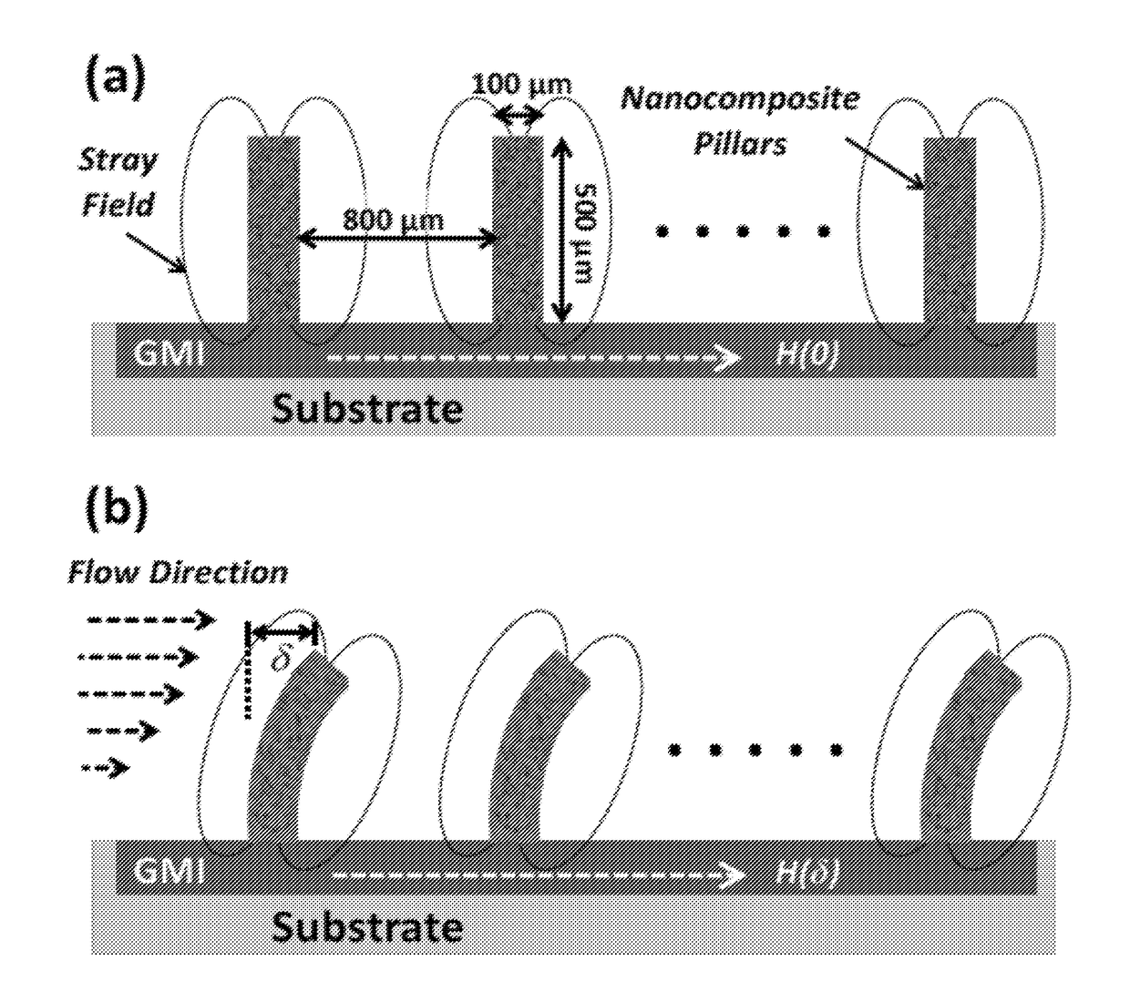
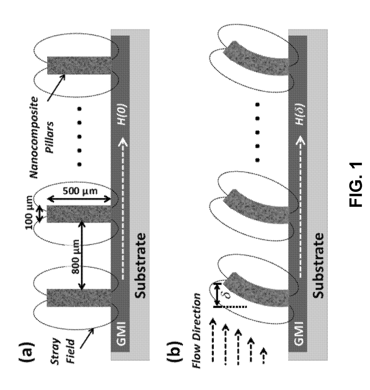
[0044]The example device illustrated in FIG. 1 is composed of magnetic nanocomposite pillars (in this example, PDMS pillars into which iron NWs are incorporated) fabricated on top of a magnetic sensor, which in turn is disposed on a substrate. A GMI sensor is used in the example shown in FIG. 1, and this sensor may be of the type described by Li et al. in “Optimization of Autonomous Magnetic Field Sensor Consisting of Giant Magnetoimpedance Sensor and Surface Acoustic Wave Transducer,”IEEE T...


PUM

PropertyMeasurementUnit
frequencyaaaaaaaaaa
velocitiesaaaaaaaaaa
power consumptionaaaaaaaaaa

Abstract

A magnetic nanocomposite device is described herein for a wide range of sensing applications. The device utilizes the permanent magnetic behavior of the nanowires to allow operation without the application of an additional magnetic field to magnetize the nanowires, which simplifies miniaturization and integration into microsystems. In5 addition, the nanocomposite benefits from the high elasticity and easy patterning of the polymer-based material, leading to a corrosion-resistant, flexible material that can be used to realize extreme sensitivity. In combination with magnetic sensor elements patterned underneath the nanocomposite, the nanocomposite device realizes highly sensitive and power efficient flexible artificial cilia sensors for flow measurement or tactile sensing.

Description

TECHNOLOGICAL FIELD[0001]Example embodiments of the present invention relate generally to force sensing and, more particularly, to a magnetic nanocomposite device providing high resolution force sensing with low power consumption.BACKGROUND[0002]Cilia are micro-scale, hair-like structures that exist in nature and extend from an organism's cells. Fish, for example, utilize cilia to assist in performing a variety of functions, such as preying or avoiding danger. In particular, when the cilia are exposed to a change in fluid flow, they bend and transmit a signal to the organism, providing the organism with sensory information enabling an appropriate reaction.[0003]Recently, artificial cilia have been developed that could be used for various applications such as microfluidic propulsion, flow sensing, or the study of cell mechanics. For the flow sensing applications, different techniques have been utilized to detect cilia bending due to flow, such as by using thermal, piezoresistive, pie...

Claims


Application Information

Patent Timeline
Patent Type & Authority Applications(United States)
IPC IPC(8): G01L1/12G01R33/09
CPCG01R33/09G01L1/12B82Y15/00G01F1/28G01L1/044G01R33/063
Inventor ALFADHEL, AHMEDLI, BODONGKOSEL, JURGEN
Owner KING ABDULLAH UNIV OF SCI & TECH
Why Eureka
Try Eureka