Imaging Mass Spectrometry Method and Device
- Summary
- Abstract
- Description
- Claims
- Application Information
AI Technical Summary
Benefits of technology
Problems solved by technology
Method used
Image
Examples
Embodiment Construction
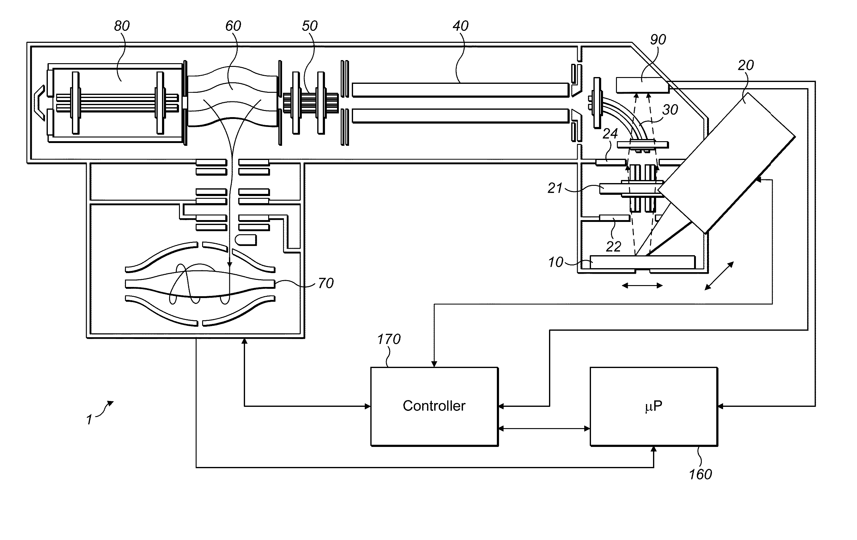
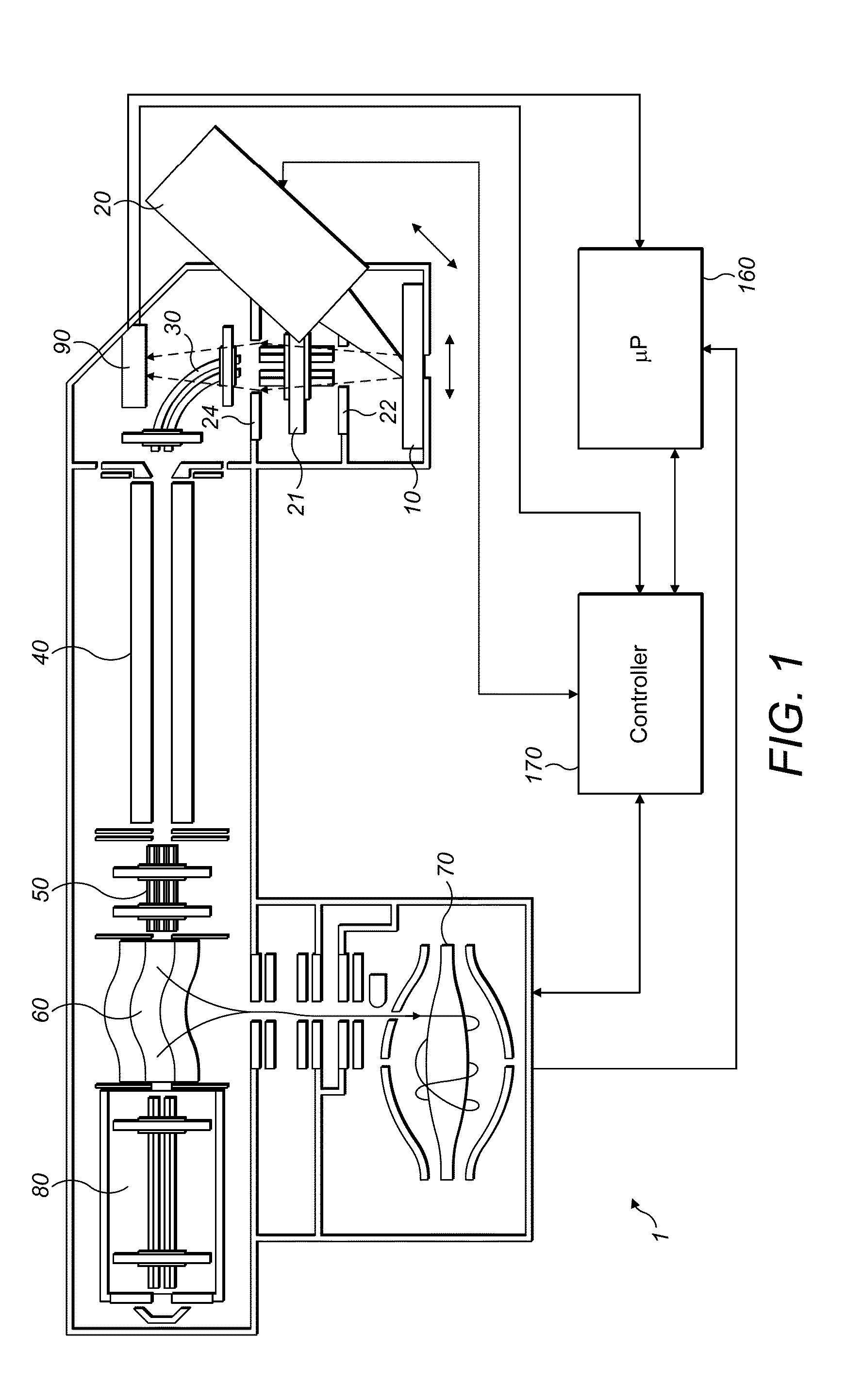
[0027]FIG. 1 shows, in schematic form, a mass spectrometer 1 in accordance with an embodiment of the present invention. The mass spectrometer 1 comprises a sample receiving portion 10, an ion source 20 such as a laser, first ion optics 21, a 2D detector 90, a quadrupole mass filter 40, second ion optics 50, a C-trap 60, an ORBITRAP™ analyser 70 and a collision cell 80.
[0028]The sample receiving portion 10 may comprise a plate. The sample receiving portion is used for supporting the sample to be analysed, i.e. imaged, as known in the art. The sample, for example, may be a tissue sample. The sample receiving portion may be mounted on a manipulator to allow rastering of the sample surface. The sample receiving portion is typically held in high vacuum (preferably at a pressure below 10−5 mbar).
[0029]The ion source 20 may comprise any suitable ionization source for time of flight (TOF) analysis, and thus is generally a pulsed ion source, or at least operable as a pulsed source for the fi...
PUM
 Abstract
Description
Claims
Application Information
 - R&D
- Intellectual Property
- Life Sciences
- Materials
- Tech Scout
- Unparalleled Data Quality
- Higher Quality Content
- 60% Fewer Hallucinations
Browse by: Latest US Patents, China's latest patents, Technical Efficacy Thesaurus, Application Domain, Technology Topic, Popular Technical Reports.
© 2025 PatSnap. All rights reserved.Legal|Privacy policy|Modern Slavery Act Transparency Statement|Sitemap|About US| Contact US: help@patsnap.com


