
Imaging mass spectrometry method and device

a mass spectrometry and mass spectrometry technology, applied in the direction of spectrometer detectors, electrical equipment, electric discharge tubes, etc., can solve the problems of affecting the use of msi in general analytical and industry practice, affecting the resolution of mass analysis data, and affecting the accuracy of mass analysis results, etc., to achieve high-resolution mass analysis data

Active Publication Date: 2016-02-16
THERMO FISHER SCI BREMEN
View PDF5 Cites 3 Cited by
  • Summary
  • Abstract
  • Description
  • Claims
  • Application Information

AI Technical Summary

Benefits of technology

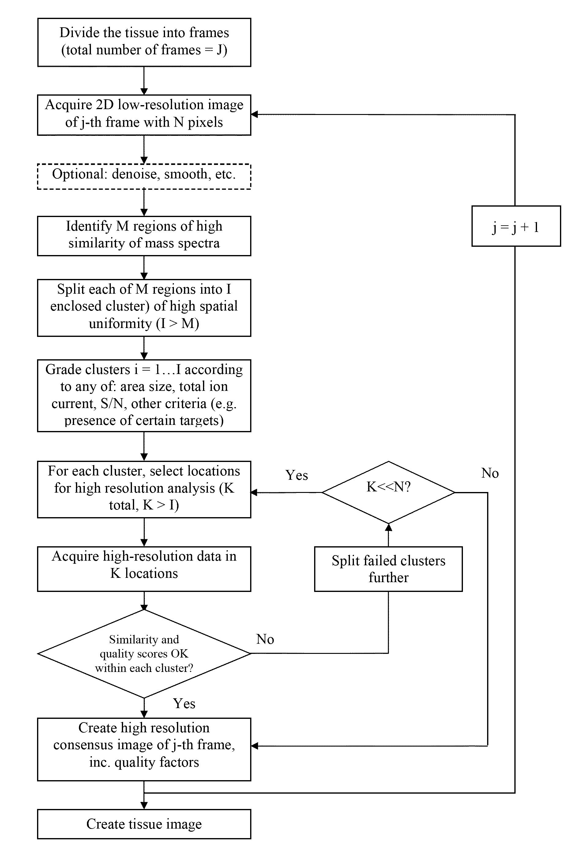
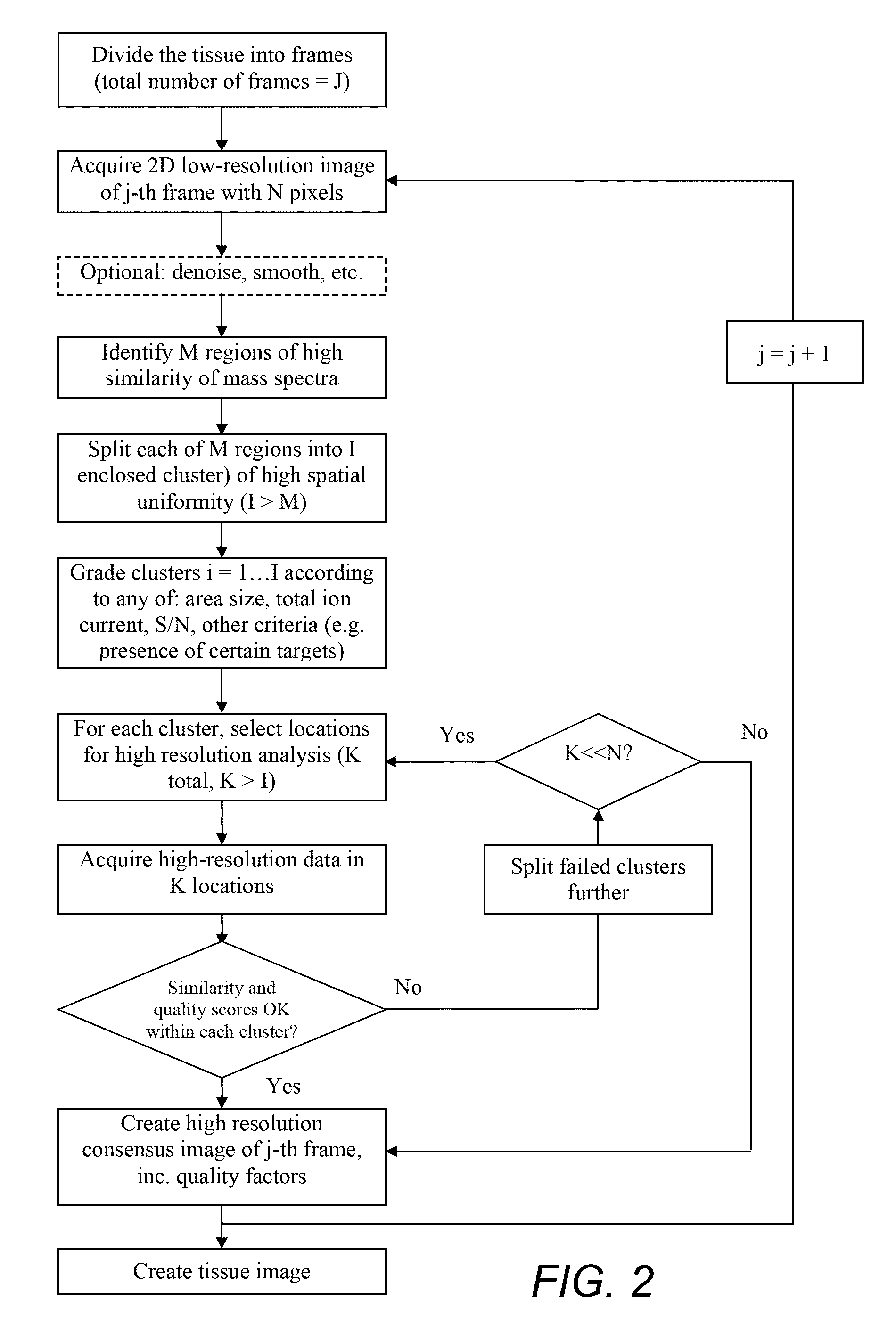
The patent describes a method for achieving higher resolution mass analysis data for a sample without having to do a higher resolution mass analysis across the entire frame or sample. This allows for faster and more accurate results at a lower cost. The apparatus can achieve high resolution mass analysis data for a sample in less time than it would take to do it for every pixel of the sample.

Problems solved by technology

Unfortunately, this rastering approach also has a significant disadvantage in that, since time of measurement is directly proportional to the number of pixels in the image, a scan might take many hours or even days.
This greatly hinders the use of MSI in general analytical and industry practice.
However, these approaches do not allow a significant reduction in the measurement time.
Though the chip allows for the possibility of acquiring tens of thousands pixels in parallel, temporal resolution of the current chip barely suffices for unit resolution up to moderate m / z (few hundreds) and does not allow resolution of isobaric interferences or effective identification of peaks.

Method used


Image

  • Imaging mass spectrometry method and device
  • Imaging mass spectrometry method and device
  • Imaging mass spectrometry method and device

Examples


Embodiment Construction

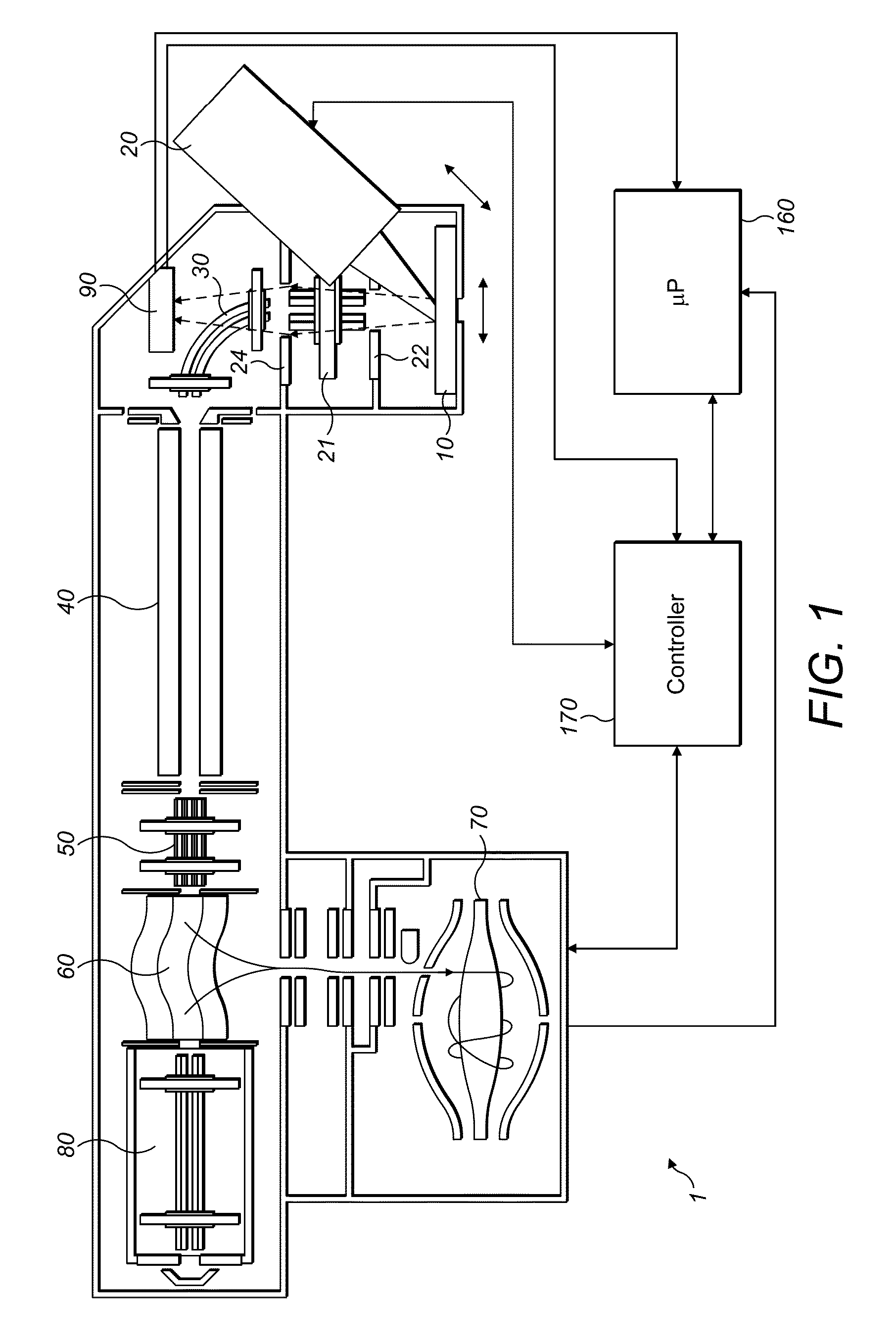
[0028]FIG. 1 shows, in schematic form, a mass spectrometer 1 in accordance with an embodiment of the present invention. The mass spectrometer 1 comprises a sample receiving portion 10, an ion source 20 such as a laser, first ion optics 21, a 2D detector 90, a quadrupole mass filter 40, second ion optics 50, a C-trap 60, an ORBITRAPanalyser 70 and a collision cell 80.

[0029]The sample receiving portion 10 may comprise a plate. The sample receiving portion is used for supporting the sample to be analysed, i.e. imaged, as known in the art. The sample, for example, may be a tissue sample. The sample receiving portion may be mounted on a manipulator to allow rastering of the sample surface. The sample receiving portion is typically held in high vacuum (preferably at a pressure below 10−5 mbar).

[0030]The ion source 20 may comprise any suitable ionization source for time of flight (TOF) analysis, and thus is generally a pulsed ion source, or at least operable as a pulsed source for the fi...


PUM


Abstract

A method of performing imaging mass spectrometry of a sample. The method comprises performing a first mass analysis of the sample using a first mass analyzer comprising a multi-pixel ion detector to obtain first mass spectral data representative of pixels of the sample. The method further comprises identifying clusters of pixels sharing one or more characteristics of first mass spectral data. The method also comprises performing a second mass analysis of the sample using a second mass analyzer to obtain second mass spectral data at at least one location in each cluster, wherein the number of locations is significantly less than the number of pixels in each cluster, said second mass analysis being of higher resolution than said first mass analysis. Also a mass spectrometry apparatus configured for carrying out the method.

Description

FIELD OF THE INVENTION[0001]The invention relates to a method of improved imaging mass spectrometry and a device for performing the same.BACKGROUND TO THE INVENTION[0002]Mass spectrometry imaging (MSI) is increasingly used for a wide range of applications, from measuring distribution of metabolites within tissues sections to histology. Spatial resolutions typically range from few to hundreds of microns.[0003]Two approaches are generally used to acquire an image of a flat sample.[0004]One approach to MSI is that of rastering, as explained in U.S. Pat. No. 5,808,300. A narrow focused ionization beam (for example, a laser beam for MALDI, LAESI, LDI, etc., primary ion beam for SIMS, primary droplet beam for DESI, primary metastable beam for DART, etc.) is used to produce ions from a small spot to be analysed by a mass spectrometer. As a surface is rastered under the beam, individual pixels are probed sequentially and corresponding data are assembled into an image. This method allows hig...

Claims


Application Information

Patent Timeline
Patent Type & Authority Patents(United States)
IPC IPC(8): H01J49/00
CPCH01J49/0004H01J49/0031H01J49/025H01J49/40H01J49/4265
Inventor MAKAROV, ALEXANDER, A.
Owner THERMO FISHER SCI BREMEN
Learn More