Microtome

Inactive Publication Date: 2017-11-23
LUTTENBERGER HERBERT
View PDF3 Cites 2 Cited by
  • Summary
  • Abstract
  • Description
  • Claims
  • Application Information

AI Technical Summary

Benefits of technology

[0012]The object of the invention is to avoid the above-described drawbacks of microtomes

Problems solved by technology

The crank handle that is provided in known microtomes is disruptive (takes up a lot of space!) and is not without its risks, since the crank handle also moves when cutting processes are carried out by motor means, e.g., in an automated operation.
Because of the number of operating elements (“buttons” and “switches”) arranged at different places in the microtome, which operating elements an operator accesses and must activate when the microtome is used, and with allowance for the fact that sections, in particular in hospitals, must be produced under time pressure, i.e., quickly and in large numbers, there is considerable

Method used


Image

  • Microtome
  • Microtome
  • Microtome

Examples


Embodiment Construction

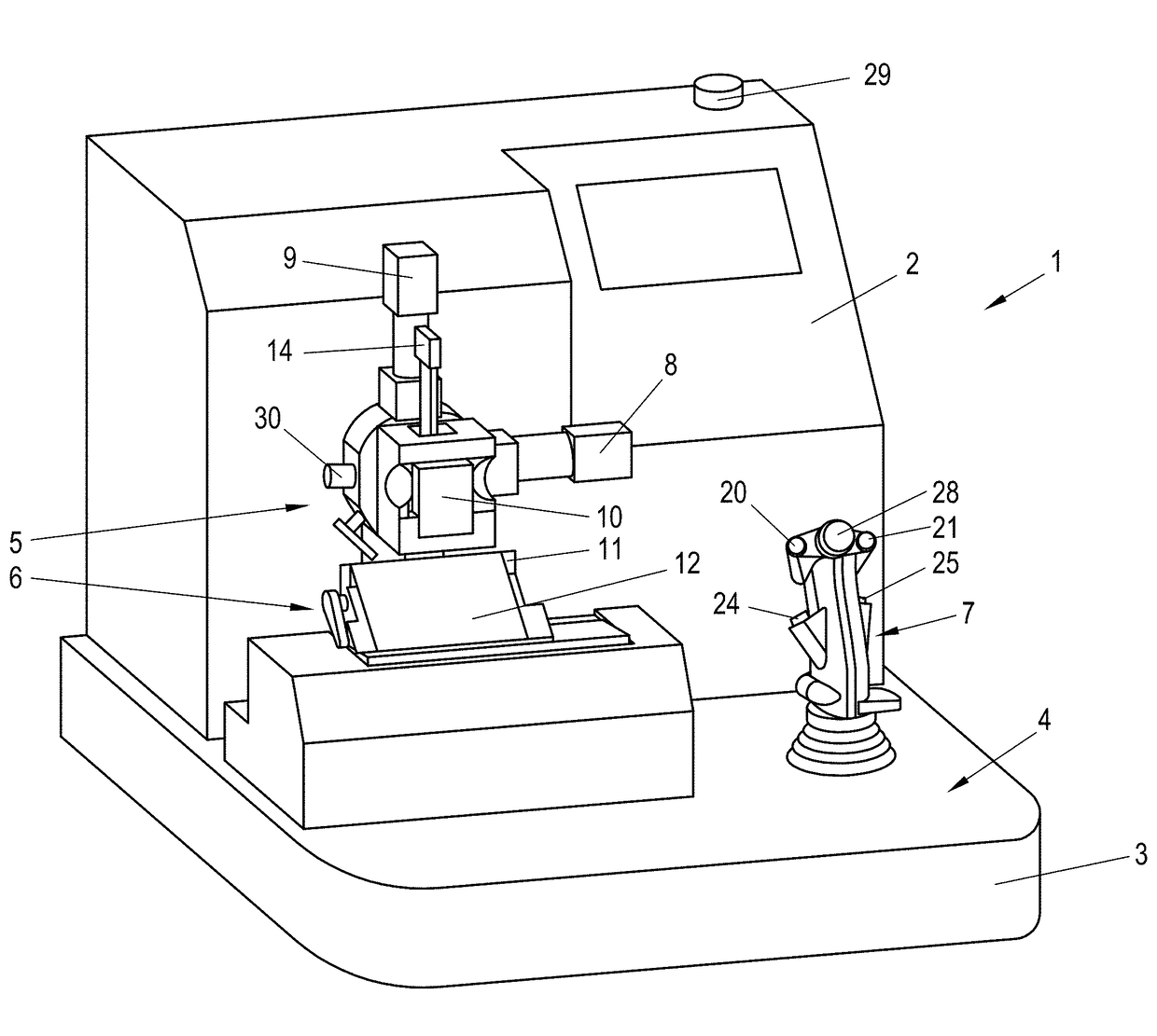
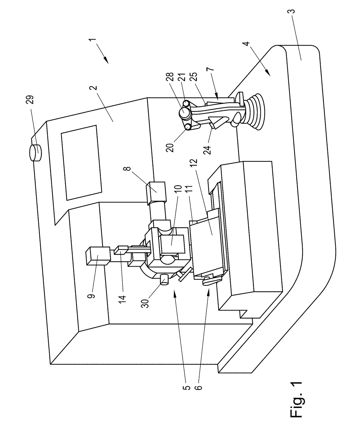
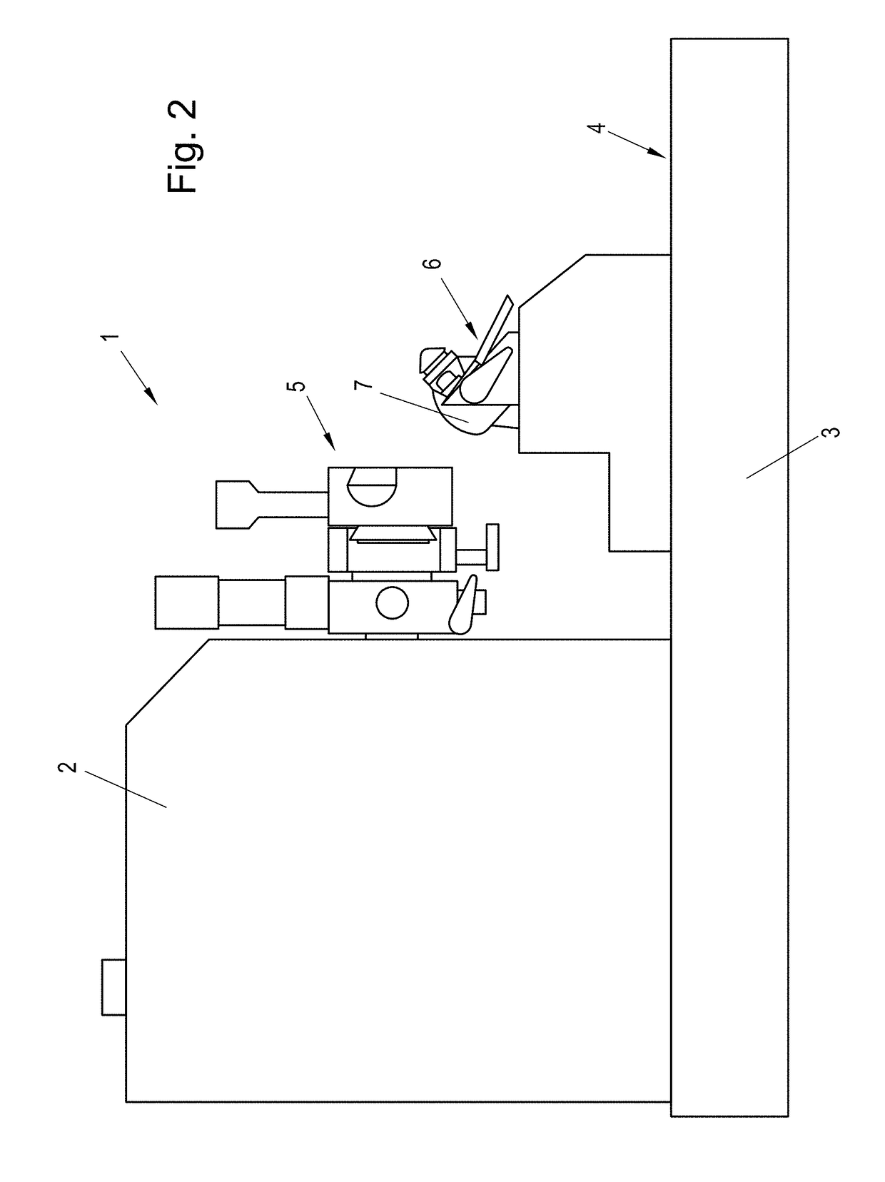
[0029]A microtome 1 that is shown in FIGS. 1 to 5 comprises a housing 2, in which additional components of the microtome according to the invention, such as drives and the like, are housed, and a base plate 3.

[0030]The microtome 1 has a preparation holding device 5, which projects forward from the housing 2 and extends above a front area 4 of the base plate 3 of the microtome 1. The drive for the motion of the preparation holding device 5 toward the base plate 3 (downward) and away from the base plate 3 (upward) is housed in the housing 2. In the case of the microtome 1 according to the invention—unlike in the case of the known microtomes—the preparation holding device 5 cannot be adjusted in a direction that is parallel to the base plate 3 (horizontal).

[0031]A knife carrier 6 is arranged in the front area 4 of the base plate 3 of the microtome 1.

[0032]In addition, a control lever 7 in the form of a joystick is provided in the front area 4 of the base plate 3 of the microtome 1 to t...


PUM


Abstract

The preparation holding device of a microtome can be pivoted via a ball head. To pivot the preparation holding device, actuators are assigned to the latter as drives. A camera and laser diodes are arranged on the knife carrier of the microtome to detect the shape and positions of the preparation.

Description

BACKGROUND OF THE INVENTIONField of the Invention[0001]The invention relates to a microtome with the features of the introductory part of claim 1.Description of the Related Art[0002]Known microtomes have a number of operating elements that are arranged at different places in the microtome and at a distance from one another and with which the microtome is adjusted, the function of the microtome is selected, and the operation of the microtome is controlled.[0003]Thus, using operating elements, the motions of the preparation holding device can be triggered to move from their readiness position into their operating position, in which the preparation is assigned to the knife of the microtome. Also, the extent of the feed stroke, i.e., the stroke of the preparation holding device before the individual cutting processes, is controlled and adjusted by operating elements.[0004]Additional operating elements are used to match the speed, at which cutting processes follow one another, to the pre...

Claims


Application Information

Patent Timeline
IPC IPC(8): G01N1/06H04N7/18
CPCG01N1/06G01N2001/066G01N2001/068H04N7/183B26D5/007B26D7/01G01N2001/065G01N2201/0612
Inventor LUTTENBERGER, HERBERTTOMIC, ROBERT
Owner LUTTENBERGER HERBERT
Why Eureka
Try Eureka