Substrate processing apparatus and substrate processing method

a substrate processing and processing apparatus technology, applied in the direction of cleaning processes and apparatus, chemistry apparatus and processes, cleaning using liquids, etc., can solve the problems of not being able to maintain low oxygen concentration and humidity, and achieve the effect of efficient replacemen

Active Publication Date: 2017-11-23
DAINIPPON SCREEN MTG CO LTD
View PDF0 Cites 20 Cited by
  • Summary
  • Abstract
  • Description
  • Claims
  • Application Information

AI Technical Summary

Benefits of technology

[0027]According to this method, the inert gas is supplied between the upper surface of the substrate and the shielding member, in a state where the atmosphere between the upper surface of the substrate and the shielding member is shielded from the ambient atmosphere. The shielding member includes an annular portion surrounding the substrate held horizontally, the atmosphere between the shielding member and the upper surface of the horizontally held substrate is thus efficiently replaced with the inert gas. The oxygen concentration and humidity in the atmosphere between the shielding member and the upper surface of the horizontally held substrate, is thereby reduced. Also, the position of the passage-allowing portion provided at the annular portion is changed by rotation of the shi

Problems solved by technology

The space on the substrate cannot be sufficiently limited, it may thus not be possible to maintain lo

Method used


Image

  • Substrate processing apparatus and substrate processing method
  • Substrate processing apparatus and substrate processing method
  • Substrate processing apparatus and substrate processing method

Examples


first preferred embodiment

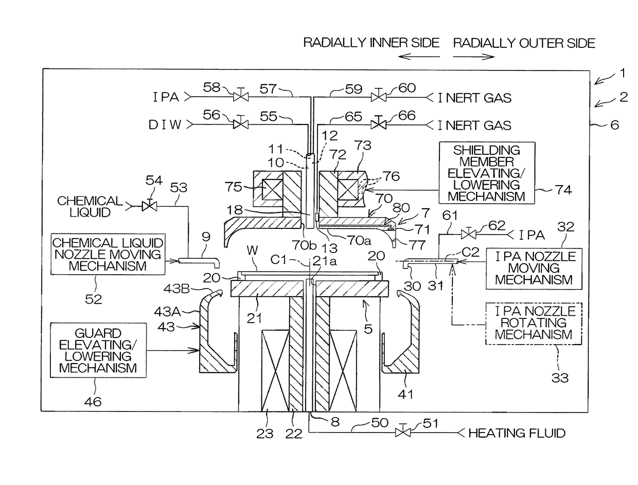
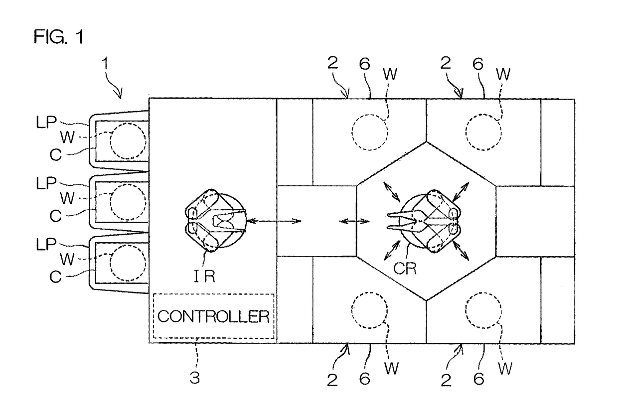
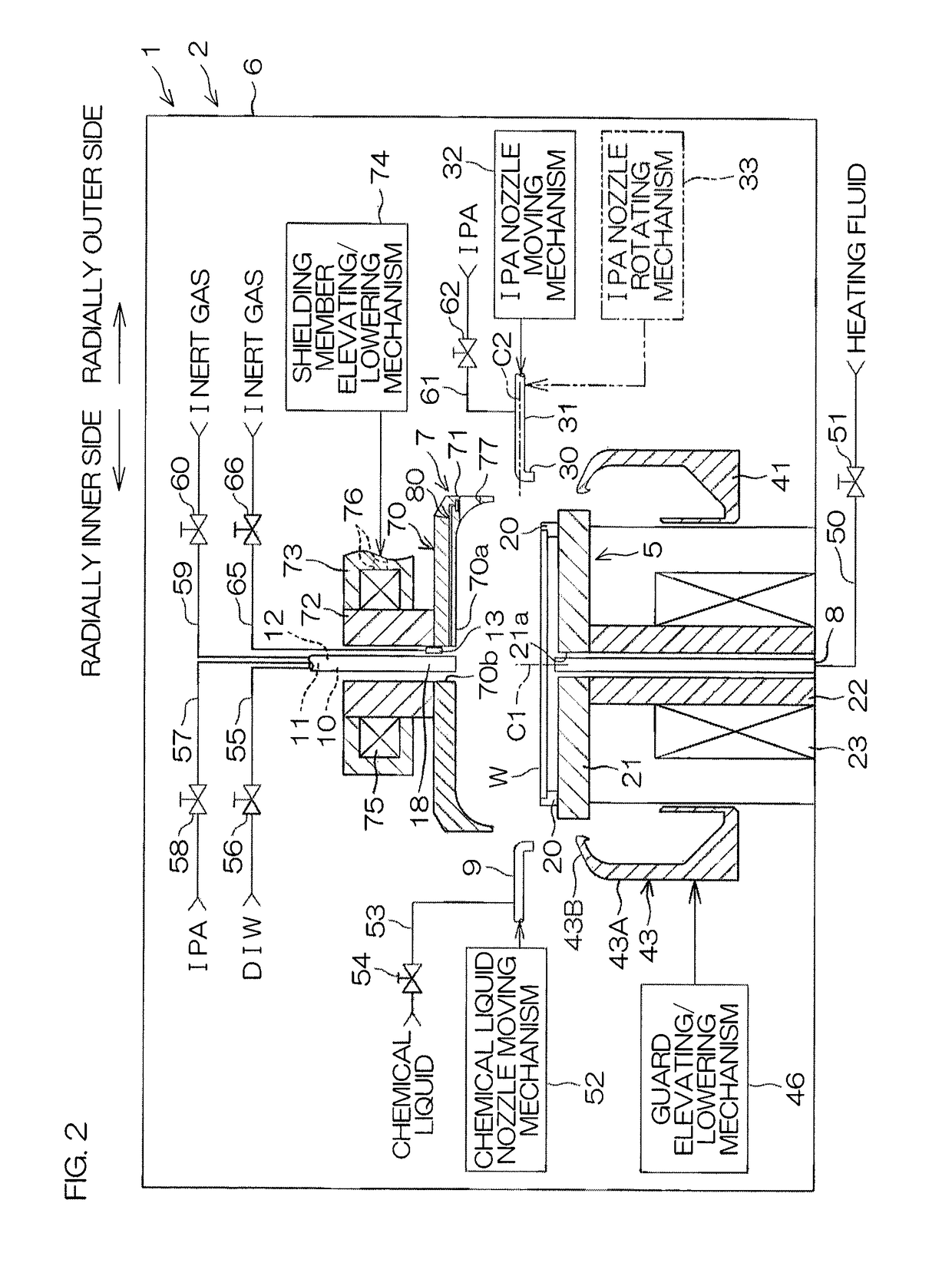
[0042]FIG. 1 is an illustrative plan view for describing a layout of an interior of a substrate processing apparatus 1 according to a first preferred embodiment of the present invention. The substrate processing apparatus 1 is a single substrate processing type apparatus that processes a substrate W such as a silicon wafer, one by one by a processing liquid.

[0043]A chemical liquid, a rinse liquid, an organic solvent, etc., can be cited as the processing liquid. In the present preferred embodiment, the substrate W is a circular substrate. A fine pattern (see FIG. 12) is formed on a front surface of the substrate W.

[0044]The substrate processing apparatus 1 includes a plurality of processing units 2, each of which processes a substrate W by the processing liquid, a plurality of load ports LP, each of which holds a carrier C that houses a plurality of substrates W to be processed by the processing units 2, transfer robots IR and CR that transport the substrates W between the load ports...

second preferred embodiment

[0157]A processing unit 2R of a substrate processing apparatus 1R according to a second preferred embodiment of the present invention will now be described. FIG. 10A and FIG. 10B are schematic cross-sectional views of the vicinity of a shielding member 7 provided in the processing unit 2R according to the second preferred embodiment. In FIG. 10A and FIG. 10B, the same members as those explained above are indicated by like reference symbols, and their explanation will be omitted.

[0158]The main point of difference of the shielding member 7 of the second preferred embodiment compared to the shielding member 7 of the first preferred embodiment (see FIG. 3) is that an annular portion 71R of the shielding member 7 of the second preferred embodiment further includes a liquid receiver 95 that receives processing liquid removed off from the substrate W, and is provided at upper side than the penetrating hole 77. Stated differently, the annular portion 71R includes an annular liquid receiver ...

third preferred embodiment

[0165]A processing unit 2S of a substrate processing apparatus 1S according to a third preferred embodiment of the present invention will now be described. FIG. 11A and FIG. 11B are schematic cross-sectional views of the vicinity of a shielding member 7 provided in the processing unit 2S according to the third preferred embodiment. In FIG. 11A and FIG. 11B, the same members as those explained above are indicated by like reference symbols, and their explanation will be omitted.

[0166]The main point of difference of the processing unit 2S of the third preferred embodiment compared to the processing unit 2 of the first preferred embodiment is that the processing unit 2S of the third preferred embodiment includes an annular portion moving mechanism 105 that moves an annular portion 71S vertically with respect to a facing portion 70S.

[0167]The facing portion 70S includes a body portion 97 that has the aforementioned facing surface 70a and communicating hole 70b and faces the upper surface...


PUM


Abstract

The substrate processing apparatus includes a substrate holding unit that holds a substrate horizontally, a substrate rotating unit that rotates the substrate held by the substrate holding unit around a prescribed rotational axis extending along a vertical direction, a processing liquid supply nozzle that moves in a horizontal direction and supplies a processing liquid onto an upper surface of the substrate held by the substrate holding unit, a shielding member that shields an atmosphere between the shielding member and the upper surface of the substrate held by the substrate holding unit from an ambient atmosphere, an inert gas supply unit that supplies an inert gas between the upper surface of the substrate held by the substrate holding unit and the shielding member, and a shielding member rotating unit that rotates the shielding member around the rotational axis. The shielding member includes an annular portion that surrounds the substrate held by the substrate holding unit, and a passage-allowing portion that is provided in the annular portion and allows the processing liquid supply nozzle to pass through the annular portion. The substrate processing apparatus includes a controller that is programmed so as to control the shielding member rotating unit to adjust a position of the passage-allowing portion in the rotational direction such that the processing liquid supply nozzle is to be passed through the annular portion.

Description

BACKGROUND OF THE INVENTION1. Field of the Invention[0001]The present invention relates to a substrate processing apparatus and a substrate processing method for processing a substrate. Examples of substrates to be processed include semiconductor wafers, substrates for liquid crystal displays, substrates for plasma displays, substrates for FEDs (field emission displays), substrates for optical disks, substrates for magnetic disks, substrates for magneto-optical disks, substrates for photomasks, ceramic substrates, substrates for solar cells, etc.2. Description of the Related Art[0002]In substrate processing by a single substrate processing type substrate processing apparatus that processes a substrate one by one, for example, a chemical liquid is supplied to the substrate that is held substantially horizontally by a spin chuck. Thereafter, a rinse liquid is supplied to the substrate and the chemical liquid on the substrate is thereby replaced by the rinse liquid. Thereafter, a spin ...

Claims


Application Information

Patent Timeline
IPC IPC(8): H01L21/67B08B3/04B08B3/08B08B3/10
CPCH01L21/67034B08B3/10B08B3/08B08B3/041H01L21/02H01L21/67017H01L21/67051H01L21/02052H01L21/68764H01L21/6719
Inventor AMAHISA, KENJIYOSHIDA, TAKESHINAMBA, TOSHIMITSU
Owner DAINIPPON SCREEN MTG CO LTD
Why Eureka
Try Eureka