Spatial Detection and Alignment of an Implantable Biosensing Platform

a biosensing platform and implantable technology, applied in the field of implantable biosensing platforms, can solve the problems of adding substantial design complexity, skin tissue makes it difficult to identify their precise location, etc., and achieves the effect of minimizing energy usage and minimizing energy usag

Pending Publication Date: 2017-11-30
BIORASIS
View PDF0 Cites 11 Cited by
  • Summary
  • Abstract
  • Description
  • Claims
  • Application Information

AI Technical Summary

Benefits of technology

[0008]In the case of miniaturized, implantable biosensors (with dimensions of few millimeters or smaller), the strong scattering nature of skin tissue makes it challenging to identify their precise location. Moreover, in order to promote patient adoption and long-term comfort (i.e. from days to years), the external device must be loosely attached to the person's body to allow sufficient skin ventilation. The latter adds substantial design complexity since implant localization must be constantly performed (typically in milliseconds range) in order to account for active lifestyles (e.g. while running), while also maintaining robust powering and communication protocols with the implant and paired external device.
[0009]This invention describes three prime examples to readily identify the spatial (x, y), depth (z) and rotational (φ) location of a miniaturized implant within highly scattering tissue; while at the same time ensuring that both the powering light source(s) and receiving photodetector(s) on the external device are situated directly over the implant and further accounting for implant rotation. These examples ensure optimal device performance with a loosely attached external device to promote patient adoption and long-term comfort:
[0016]A method for spatial detection of a miniaturized fully implantable biosensor within a body tissue is provided, wherein the method comprises magnetic alignment and minimizes energy usage via an algorithm facilitating alignment for both optical powering and optical communication units, wherein the algorithm is located in the microprocessor of an external control unit which interfaces with a miniaturized biosensor platform, wherein the algorithm interfaces with an array of magnetic field detecting sensors, an array of light emitters, and an array of light photodetectors within the said external control unit, wherein the algorithm also interfaces with powering source, data acquisition module, display, magnetic field sources, and other components within the external control unit, wherein said algorithm interfaces with the miniaturized biosensor platform through its light powered photovoltaic cells and one or more light emitters that optically transmits the detected concentration values of various analytes to the external control unit, wherein the algorithm senses the position of the miniaturized biosensor platform through the mapping of the magnetic field generated by one or more miniaturized magnets located on it, and imaged by the magnetic field detecting sensor array in the external unit to provide the precise assessment of the spatial (x, y) position, depth (z) and rotational (φ) state of the implantable biosensor platform, wherein the algorithm uses the precise spatial (x, y) position to turn on one or more light emitters in the array of the external control unit, which are aligned by line-of-sight with the miniaturized biosensor platform, wherein the algorithm uses the depth and rotational coordinates information to adjust the output light intensity of the selected light emitters, as well as power adjacent light emitters to compensate for the rotation of the photovoltaic cells wherein the algorithm uses the precise spatial and rotational position to turn on one or more photodetectors in the array of the external control unit that are also aligned with the miniaturized biosensor platform, wherein the algorithm accounts for changes in the spatial position and orientation of the external control unit with respect to the miniaturized biosensor platform to account for random motion caused by intense physical activity of the user.
[0017]A method for spatial detection of a miniaturized fully implantable biosensor within a body tissue is provided that comprises optical alignment and minimizes energy usage via an algorithm facilitating alignment for both optical powering and optical communication units, wherein the algorithm is located in the microprocessor of an external control unit which interfaces with a miniaturized biosensor platform, wherein the algorithm interfaces with an array of light emitters, and a array of light photodetectors within the external control unit, wherein the algorithm also interfaces with powering source, data acquisition module, display, and other components within the external control unit, wherein the algorithm interfaces with the miniaturized biosensor platform through its light powered photovoltaic cells and a pair of light emitters oriented at about 90° from each other and at about 45° with respect to the bottom of the external control unit, wherein the algorithm senses the position of the miniaturized biosensor platform through the mapping of the intensity generated on the array of light photodetectors to provide the precise assessment of the spatial (x, y) position, depth (z) and rotational (□) state of the implantable biosensor platform, wherein the algorithm uses the precise spatial (x, y) position to turn on one or more light emitters in the array of the external control unit, which are aligned by line-of-sight with the miniaturized biosensor platform, wherein the algorithm uses the depth and rotational coordinates information to adjust the output light intensity of the selected light emitters, as well as power adjacent light emitters to compensate for the rotation of the photovoltaic cells wherein the algorithm uses the precise spatial and rotational position to turn on one or more photodetectors in the array of the external control unit that are also aligned with the miniaturized biosensor platform, wherein the algorithm accounts for changes in the spatial position and orientation of the external control unit with respect to the miniaturized biosensor platform to account for random motion caused by intense physical activity of the user.

Problems solved by technology

In the case of miniaturized, implantable biosensors (with dimensions of few millimeters or smaller), the strong scattering nature of skin tissue makes it challenging to identify their precise location.
The latter adds substantial design complexity since implant localization must be constantly performed (typically in milliseconds range) in order to account for active lifestyles (e.g. while running), while also maintaining robust powering and communication protocols with the implant and paired external device.

Method used


Image

  • Spatial Detection and Alignment of an Implantable Biosensing Platform
  • Spatial Detection and Alignment of an Implantable Biosensing Platform
  • Spatial Detection and Alignment of an Implantable Biosensing Platform

Examples


second embodiment

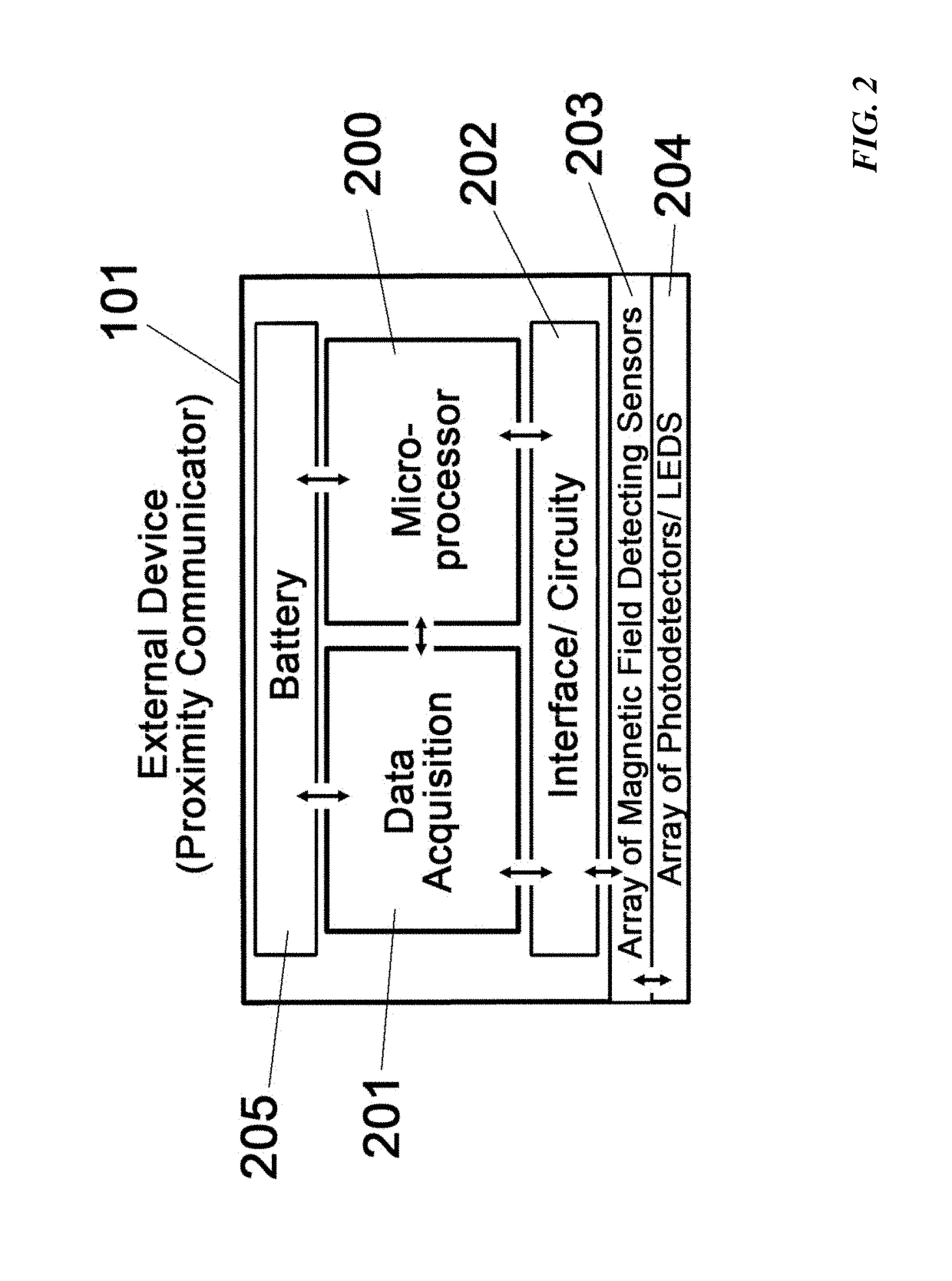
[0040]Additional circuitry 202 such as an embedded processing unit 200 or circuitry to connect to an external computer may be implemented into the proximity communicator. Software or computer algorithms are then used to store and analyze the electrical signals of the magnetic field detecting sensors. In one embodiment, the magnetic field detecting sensors produce a digital signal and an extensive array of such sensors covering a ROI can be used to represent the spatial location of the fully implantable biosensor. In a second embodiment, the analog output voltage from each hall-effect sensor over a specific surface area can be used to map the location of any magnetic material under the skin. In this embodiment, the x-y position can be determined by the array of magnetic field detecting sensors and the z-position can be determined by the analog signal strength (e.g. output voltage). Moreover, magnetic field detecting sensors can detect the orientation and rotational (φ) location of a ...

example b

[0046 utilizes magnetic interacting / polarizing materials and devices (i.e. coils) within the implanted biosensor to alter the magnetic field pattern produced by a permanent (FIG. 9a) or oscillating (FIG. 9b) magnetic field generators situated within the external device. Such magnetic field alteration is detected by the array of magnetic field detecting sensors described above and used to assess the spatial (x, y), depth (z) and rotational (φ) position of the miniaturized implant within a highly scattering tissue.

[0047]Two exemplary devices and methods for the spatial localization of the implanted biosensor using magnetic interacting / polarizing materials and devices are shown in FIG. 9. Here the implant is outfitted with magnetically interacting / polarizable materials and devices 930 (i.e. coils 901 and complex 2D and 3D architectures with or without cores 902 of magnetic polarizable substances, like spin-glass). Subcategories of magnetically polarizable material include traditional m...

example c

[0049 describes another exemplary device and method for the spatial localization of the implant without the use of permanent magnets that can be incompatible with MRI. This approach negates completely the need for the array of magnetic field detecting sensors 203 and relies solely on the array of photodetector (PD) and LEDs 204 of the external device (proximity communicator) to map the emission from the two on-board LEDs or lasers (502 and 503) within the implantable biosensor 102 (FIG. 11). The two on-board light sources are oriented at 90° with each other in order to provide differential PD response upon φ rotation (although their relative orientation can greatly vary). FIG. 11 illustrates three exemplary PD line responses for φ of 0°, 45° and 90°. Since the front on-board light source 502 lines up with PD line #1 and the back on-board light source 503 lines up with PD line #2, different response patterns will be obtained depending on the specific rotation of the implant. These pa...


PUM


Abstract

A system and method is outlined for a wearable external device that communicates with a fully implantable miniaturized biosensor platform providing fast spatial detection and accurate assessment of the position and orientation of the implant within highly scattering tissue. The device and method provides spatial (x, y) position, depth (z) and rotational (φ) state of the implantable biosensor platform. The spatial (x, y) position allows the ability to turn-on only one out of an entire array of LEDs that is in line-of-sight with the implant in order to conserve power. Similarly, the depth and rotational coordinates information is used to adjust the output light intensity of the selected light emitters to compensate the power delivered to the implant. The above attributes render the system compatible for usage during intense physical activity and for added user comfort through improved skin ventilation.

Description

CROSS REFERENCE TO RELATED APPLICATIONS[0001]This application is related to and claims the benefit of the filing date of U.S. Provisional Patent Application Ser. No. 62 / 307,443 filed Mar. 12, 2016, the contents of which are incorporated herein by reference in its entirety.STATEMENT REGARDING FEDERALLY SPONSORED RESEARCH[0002]The United States Government has certain rights in this invention pursuant to U.S. Army Medical Research and Materiel Command Grant No. W81XWH-15-C-0069.FIELD OF THE INVENTION[0003]The present invention relates generally to implantable biosensing platforms and more specifically to the detection and alignment of the implantable biosensing platforms.BACKGROUND OF THE INVENTION[0004]Biosensing platforms, or biosensors, for medical applications have significant promises as a means to diagnose and to manage diseases. A biosensor can be any device that detects any chemical or physical change, converts that signal into an electrical or chemical signal and transmits the...

Claims


Application Information

Patent Timeline
Patent Type & Authority Applications(United States)
IPC IPC(8): A61B5/07A61B5/145A61B5/06A61B5/00A61B5/055
CPCA61B5/076A61B5/062A61B5/0084A61B5/055A61B2560/0219A61B5/14503A61B2562/0223A61B2562/0238A61B5/742
Inventor JAIN, FAQUIRPAPADIMITRAKOPOULOS, FOTIOSCOSTA, ANTONIOKASTELLORIZIOS, MICHAILLEGASSEY, ALLEN
Owner BIORASIS
Why Eureka
Try Eureka