
Pressure Output Device For Extracorporeal Hemodialysis Machine

a technology of output device and hemodialysis machine, which is applied in the direction of fluid pressure measurement using elastically deformable gauges, instruments, other medical devices, etc., can solve the problems of reducing treatment effectiveness, affecting the accuracy of arterial pressure measurement, and reducing treatment effectiveness, so as to minimize the potential for hazardous restriction, facilitate many functions, and accurately communicate arterial pressure

Active Publication Date: 2017-11-30
FRESENIUS MEDICAL CARE HLDG INC
View PDF30 Cites 8 Cited by
  • Summary
  • Abstract
  • Description
  • Claims
  • Application Information

AI Technical Summary

Benefits of technology

The present invention provides a liquid processing circuit with a pressure output device that can be used in an extracorporeal hemodialysis circuit. The device can accurately measure and communicate blood circuit pressure without exposing it to air, minimizing potential hazardous conditions. It can also prevent blood contamination and protect the pressure transducer from blood contact. The device can be placed along the arterial and venous lines of the circuit and used during hemodialysis. It provides an airless system for transferring extracorporeal circuit pressures to the pressure monitoring ports of the dialysis machine. The device has two chambers separated by an elastomeric diaphragm, with one chamber containing air and the other chamber containing blood. The device protects the pressure transducer from blood contact and provides a sterile barrier at the interface to the blood circuit. The device can accurately communicate arterial and venous pressures even at elevations of up to 8000 feet. The device can be designed with different internal volumes to achieve accurate pressure sensing within a range of from 0 to −300 mmHg and from 0 to 500 mmHg.

Problems solved by technology

Problems with such a blood-air interface system include clotting, heparin dosage concerns, contamination, and inaccurate pressure measurements.
Air contact with blood results in clotting that can collect in portions of the blood circuit, reducing treatment effectiveness.
The use of heparin adds cost to the treatment and increases the potential for hazardous blood loss.
The hydrophobic membrane in the transducer protector is very thin, and occasionally allows blood contamination of the pressure monitoring circuit on the dialysis machine.

Method used


Image

  • Pressure Output Device For Extracorporeal Hemodialysis Machine
  • Pressure Output Device For Extracorporeal Hemodialysis Machine
  • Pressure Output Device For Extracorporeal Hemodialysis Machine

Examples


Embodiment Construction

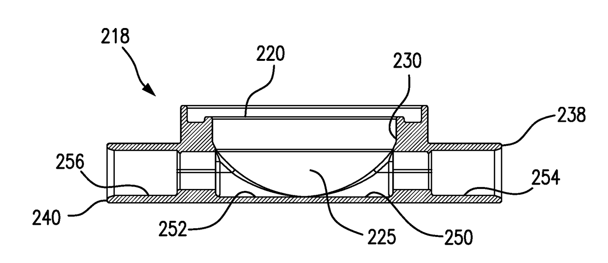
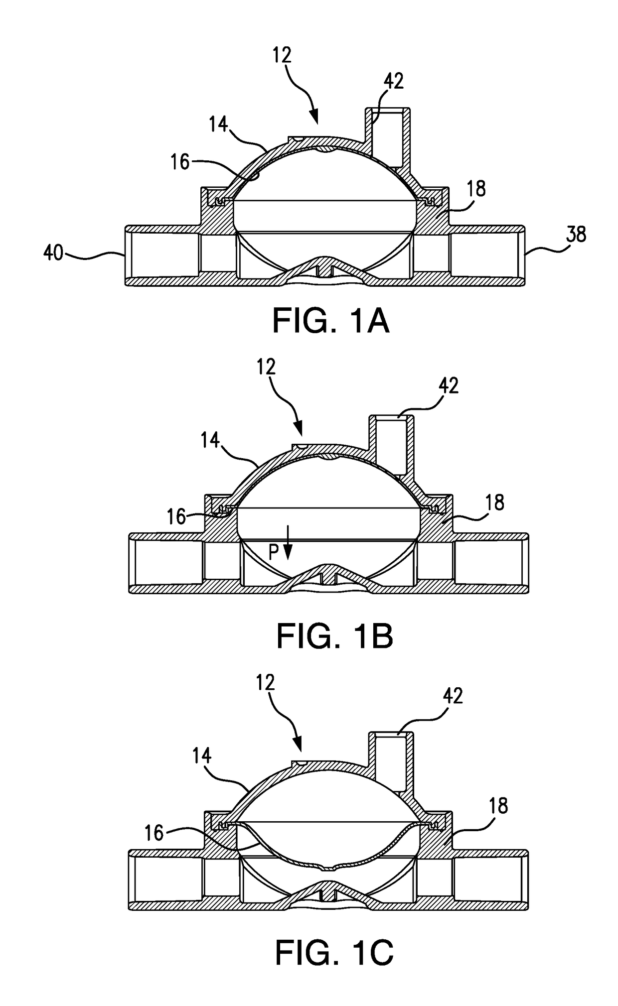
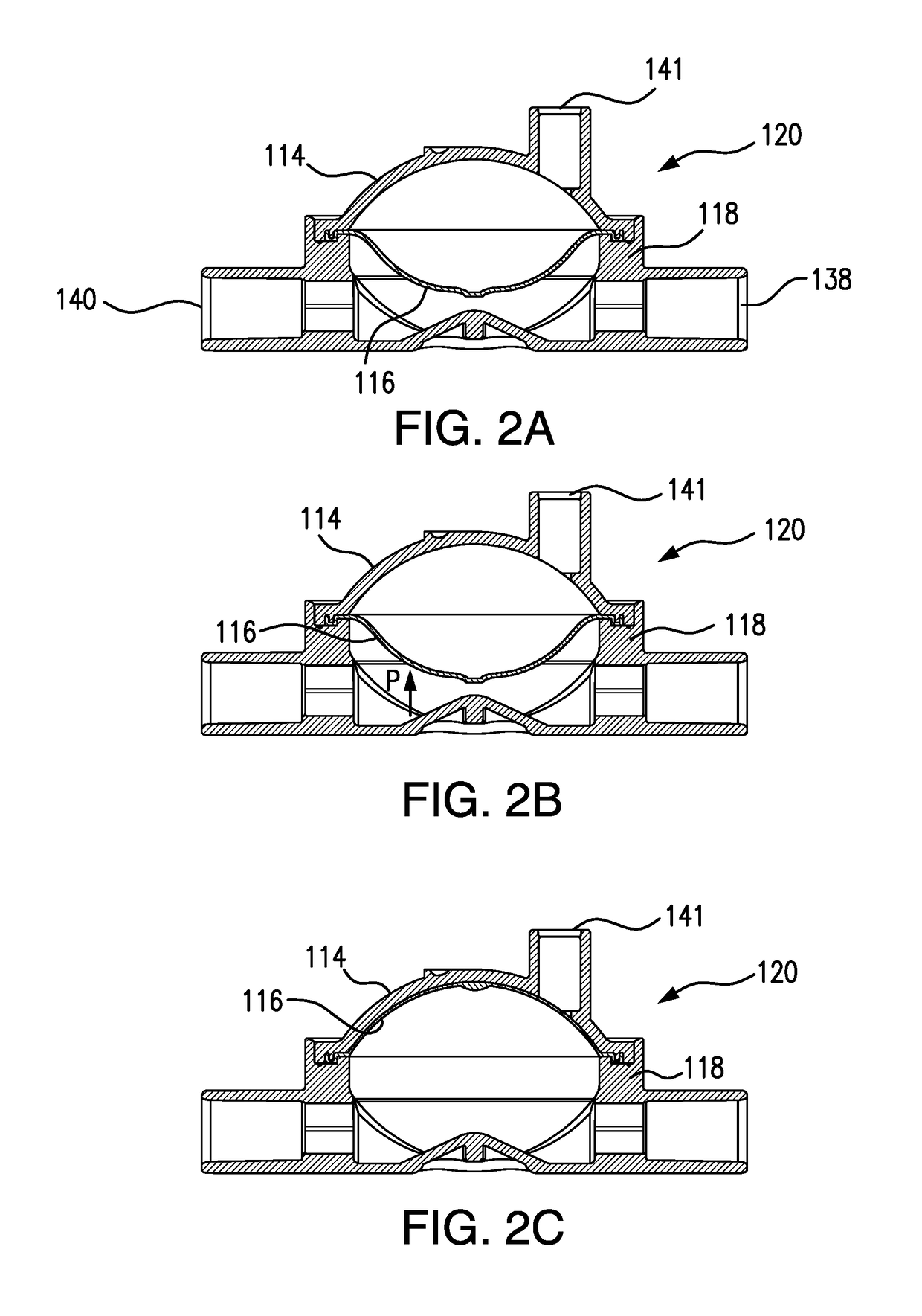
[0045]FIGS. 1A-1C are cross-sectional side views of an assembled pressure output device (POD) according to one or more embodiments of the present invention and arranged to measure blood pressure in an arterial circuit. POD assembly 12 is constructed of a cap 14, a diaphragm 16, and a base 18, assembled together. Blood tubing can be connected, for example, by solvent-bonding, to an inlet port 38 and an outlet port 40 on the flow-through side or chamber of the POD assembly. A sensor port 42 is provided in cap 14 and tubing can be connected, for example, by solvent-bonding, to form a communication between sensor port 42 and a pressure sensor port of a hemodialysis machine. For the purpose of simplification, the respective tubings are not shown in FIGS. 1A-2C.

[0046]FIG. 1A shows diaphragm 16 in an initial, start position for an arterial circuit. POD assembly 12 is arranged to measure negative pressures, i.e., sub-atmospheric pressures. Diaphragm 16 in FIG. 1A is shown as positioned at z...


PUM


Abstract

A pressure output device (POD) assembly for sensing fluid pressure in a fluid processing system, is provided. This POD assembly includes a shell defining a shell interior, and a movable diaphragm disposed in the shell interior and separating the shell interior into a flow-through chamber and a pressure sensing side. A sensor port is in fluid communication with the pressure sensing side. An inlet port and an outlet port are in fluid communication with the flow-through chamber. The inlet port and the outlet port define an inlet and an outlet, respectively, of a flow-through channel that passes through the flow-through chamber. A boss protrudes from the interior wall of the shell and extends into the flow-through channel to prevent occlusion of flow under different pressure conditions within the flow-through chamber.

Description

CROSS-REFERENCE TO RELATED APPLICATION[0001]This application is a continuation of U.S. patent application Ser. No. 14 / 810,526, filed Jul. 28, 2015, which, in-turn, claims the benefit under 35 U.S.C. §119(e) of U.S. Provisional Patent Application No. 62 / 056,122, filed Sep. 26, 2014, the entire contents of both of which are hereby incorporated by reference.FIELD OF THE INVENTION[0002]The present invention relates to pressure output devices for measuring fluid pressure in an extracorporeal hemodialysis machine.BACKGROUND OF THE INVENTION[0003]Hemodialysis machines commonly monitor pressure in an extracorporeal blood circuit, for example, pressure from a blood chamber containing a blood-air interface. An air-filled tube connects the blood chamber to a pressure port of the machine. A transducer protector, containing a hydrophobic membrane, is positioned between the blood chamber and the pressure port. The membrane provides a sterile barrier to the blood circuit and prevents blood contami...

Claims


Application Information

Patent Timeline
Patent Type & Authority Applications(United States)
IPC IPC(8): A61M1/36A61M39/22G01L7/08G01L19/06G01L19/00
CPCA61M39/227A61M1/3641A61M2205/3331A61M2205/12G01L19/0618G01L19/0023A61M1/3639G01L7/082G01L7/08A61M1/1621
Inventor LINDLEY, DELOYBADILLO, JOSE ANTONIOSMITH, MICHAEL PARRYLASHER, RICHARD ALLENDAYTON, TROY CALVINJENSEN, LYNN E.
Owner FRESENIUS MEDICAL CARE HLDG INC
Learn More