Hydrocarbon Well Production Analysis System

a well and production analysis technology, applied in the field of on-site analysis of fluids, can solve the problems of insufficient gravity alone, difficult to determine relative percentages of emulsions, and high cost of separation devices, so as to facilitate maintenance and repair, and efficiently sweep the cylinder clear

Inactive Publication Date: 2017-11-30
DWT SOLUTIONS
View PDF4 Cites 3 Cited by
  • Summary
  • Abstract
  • Description
  • Claims
  • Application Information

AI Technical Summary

Benefits of technology

[0014]It is to be noted that the presently disclosed invention can utilize almost any of the types of devices for the eventual water cut determination. The presently disclosed invention improves the accuracy of these devices by providing a sample, on the fly at real-time conditions, where the sample is essentially gas free and, optionally, heated to API standard temperature for water cut determination. The inventor herein has found that PHASE DYNAMIC water cut analyzers, which utilize the difference between the electrical characteristics of the water and oil to determine water content, are acceptable for use for water cut determination, but other water cut analyzers may be utilized as well.
[0017]The piston utilized in the cylindrical vessel may be configured with a piston head and seals which efficiently sweep the cylinder clear of all fluids contained within the cylinder, such that there is little or no mingling of samples as each sample is processed through the system. The cylinder wall may be lined with a material which is non-stick and capable of receiving high temperature fluids.
[0019]It should be understood that all sensors utilized with embodiments of the device may be located outside of the cylindrical vessel, which greatly facilitates maintenance and repair. In addition, the sensors may be of the type which provide output signals compatible for receipt as input to a digital processor for either data collection or control purposes.

Problems solved by technology

However, particularly with heavy crudes which may have gravities approaching that of water, gravity alone is not always sufficient.
Emulsions also present difficulties in determining the relative percentages of water and oil in a well's production stream.
These separation devices are expensive and typically require a given volume of produced fluid to remain in the test vessel for sufficient time to allow oil and water separation.
However, this operation is time consuming and requires manual processing of the sample.
It is not a method which may be replicated in the field for real time determination of water cut.

Method used


Image

  • Hydrocarbon Well Production Analysis System
  • Hydrocarbon Well Production Analysis System
  • Hydrocarbon Well Production Analysis System

Examples


Embodiment Construction

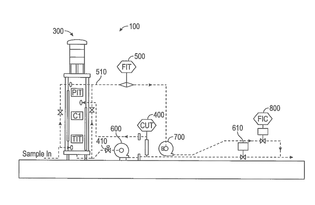
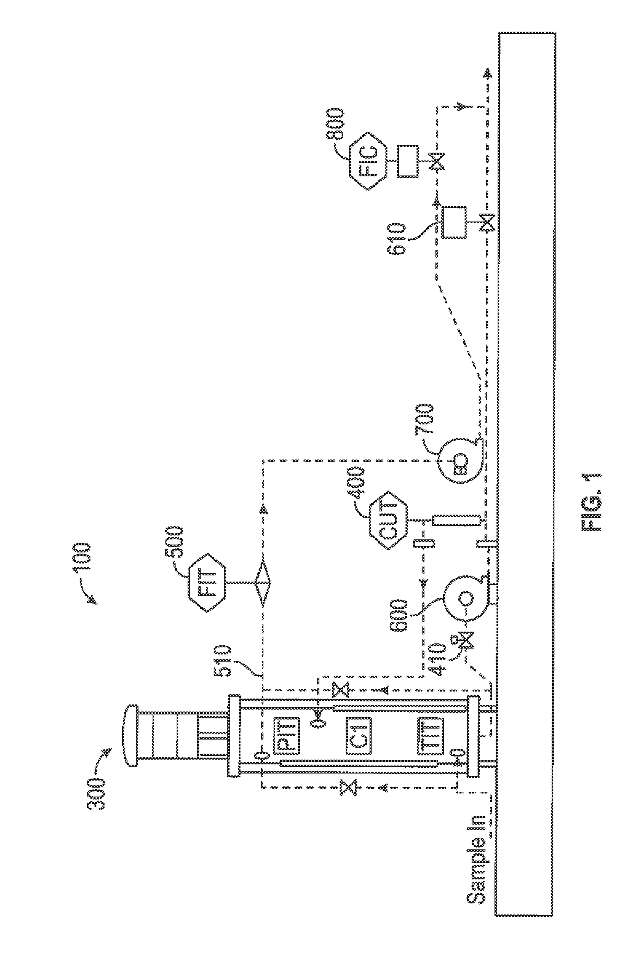
[0038]FIG. 1 schematically depicts an embodiment of the presently disclosed hydrocarbon well production analysis system 100 according to the present invention. A fluid sampling system 200 for obtaining a representative fluid sample from pipeline 10 is described in further detail below. With respect to the hydrocarbon analysis system depicted in FIG. 1, the major components of this embodiment include cylindrical vessel 300, water cut analyzer 400, gas flow meter 500, circulating pump 600, gas compressor 700, and flow control valve 800. A digital processor 1000, not shown in FIG. 1, provides, among other things, control of the process flow of the analysis system and reporting of the analysis results. It is to be appreciated that the components of the production analysis system 100 may be relatively small, fitting within an instrument cabinet or mounted on a transportable skid for easy movement between locations. Flow volumes may be relatively small and interconnecting piping may be ½ ...


PUM


Abstract

An oil well production analyzing system receives production fluid samples from the oil well according to an automated sampling schedule. The fluid samples are taken from a pipeline through a sampling apparatus to obtain a representative sample. The representative sample flows into a circulation loop having a circulating pump, a water cut analyzer, and a cylindrical vessel, with interconnecting piping and actuated valves there between, with the actuated valves and the circulating pump controlled by a digital processor. Once a determination of the percentage of water and oil in the sample has been determined, the processor stops the circulating pump and activates a piston in the cylindrical vessel which sweeps the cylindrical vessel of any fluid contained in the vessel in preparation of receiving a subsequent fluid sample from the oil well.

Description

BACKGROUND OF THE INVENTION[0001]The present invention generally relates to the on-sight analysis of fluids produced from hydrocarbon producing wells and the measurement of flow rates of those fluids. In particular, the present invention relates to devices which provide real-time determination of the relative components of the fluids produced from hydrocarbon producing wells and the flow rates of each of the relative components, both instantaneous and over a particular period of time.[0002]A determination of the percentage of water with respect to the volume of total liquids produced by the well—the “water cut”—is important for determination of the economic viability of a well because excessive water production increases lifting and separation expense, plus the produced water must be properly disposed. In addition, an accurate real-time determination of water cut, when used in conjunction with other parameters such as oil gravity and gas liquid ratio, may be utilized to determine th...

Claims


Application Information

Patent Timeline
Patent Type & Authority Applications(United States)
IPC IPC(8): E21B47/10
CPCE21B47/10G01N1/10E21B49/086G01F1/74E21B49/087
Inventor MARSHALL, DAN W.
Owner DWT SOLUTIONS
Why Eureka
Try Eureka