

Imaging system with oblique illumination
a technology of oblique illumination and imaging system, which is applied in the field of imaging system, can solve the problems of increasing the cost and complexity of the microscop
- Summary
- Abstract
- Description
- Claims
- Application Information
AI Technical Summary
Benefits of technology
Problems solved by technology
Method used
Image

Examples
example 1
ystem with Obliquely-Oriented LEDs
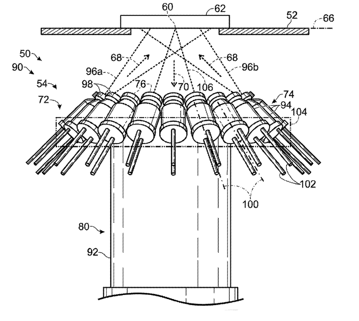
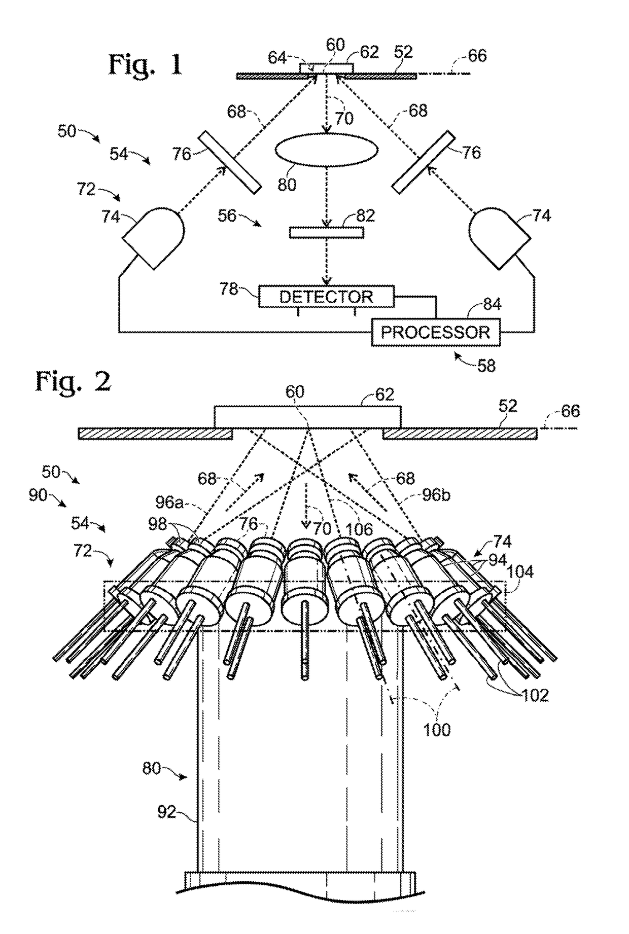
[0046]This example describes a first exemplary embodiment 90 of imaging system 50, with the system having a source assembly with obliquely-oriented light-emitting diodes (LEDs) as light sources; see FIG. 2 (also see FIG. 1).
[0047]Imaging system 90 has an illumination subsystem 54 incorporating an annular source assembly 72 mounted to a housing 92 of an objective 80. Source assembly 72 is centered on detection optical path 70.
[0048]The source assembly has a plurality of solid-state light sources 74, namely, LEDs 94. The flux of light 96a, 96b (e.g., excitation light) from the source assembly is indicated in FIG. 2 for only two LEDs 94, with the light traveling along respective illumination optical paths 68 from the two LEDs. However, any suitable number of the LEDs may be on (energized) at the same time. Energizing multiple LED copies, each having the same spectral output, can increase flux and homogenize irradiance by superimposing their cones of li...
example 2
ystem with Parallel LEDs
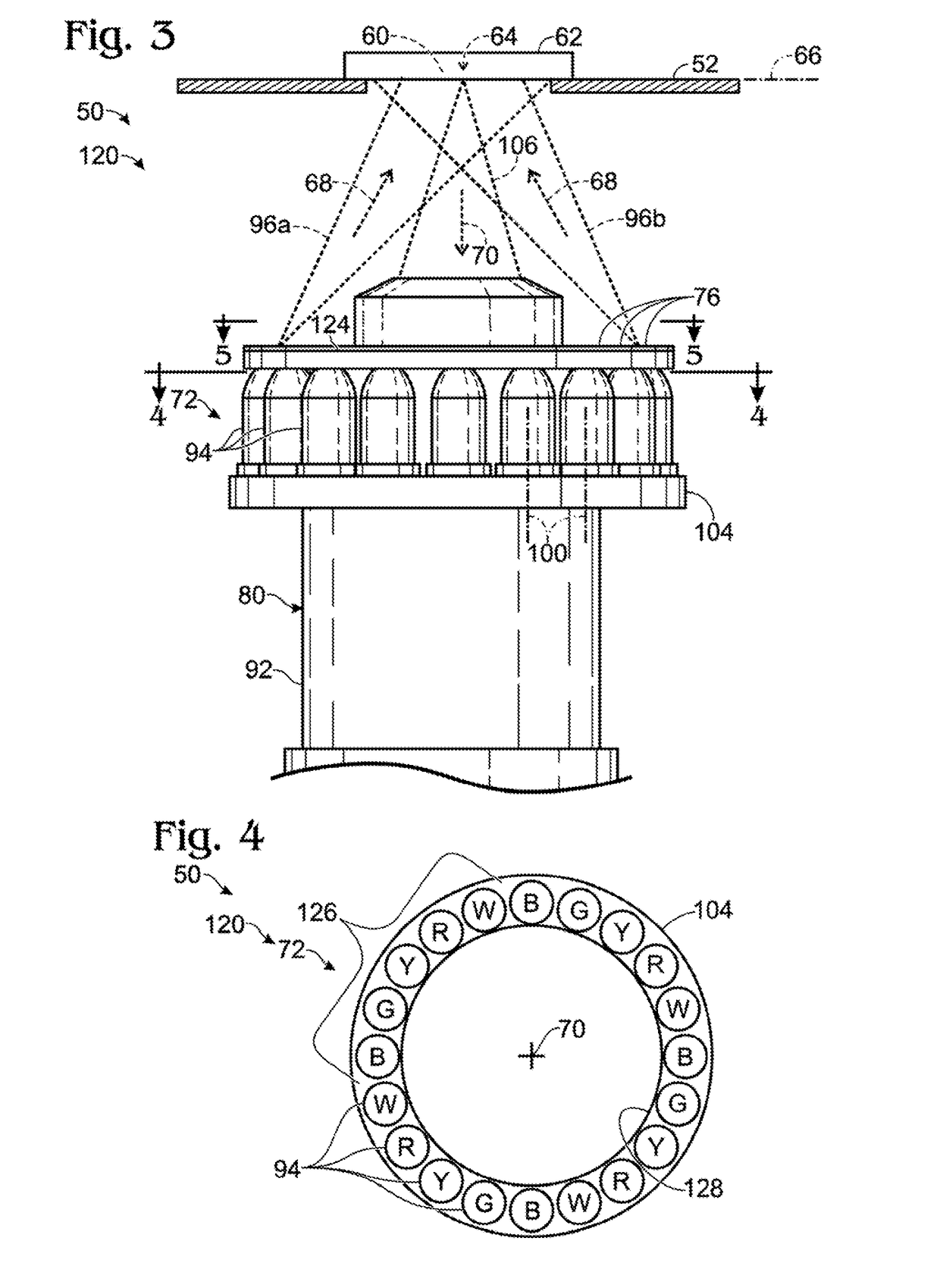
[0053]This example describes a second exemplary embodiment 120 of imaging system 50, with the system having a source assembly with parallel LEDs as light sources; see FIGS. 3-6 (also see FIG. 1).
[0054]Imaging system 120 is constructed generally as described above for imaging system 90 of FIG. 2 but has a different source assembly 72. Annular frame 104 holds LEDs 94 in a ring, as in the source assembly of imaging system 120, but central axes 100 of the LEDs are parallel to one another, orthogonal to sample plane 66, and parallel to detection optical path 70. Also, dedicated lenses 98 of imaging system 90 in FIG. 2 are replaced by a single shared Fresnel lens 124 that is configured to focus a beam of light from each LED onto sample plane 66. The Fresnel lens may provide a substrate to which each spectral filter 76 is attached, e.g., as a coating on the non-grooved side of the lens.
[0055]FIG. 4 shows a plan view of source assembly 72 of imaging system 120 taken ...
example 3
ystem with Illumination Via an Objective
[0061]This example describes a third exemplary embodiment 140 of imaging system 50, with the system having an objective 80 that transmits light from an annular source assembly 72 to the sample; see FIG. 7 (also see FIG. 1).
[0062]Source assembly 72 of imaging system 140 is structured generally as in imaging system 120 but is located near or at the bottom end of objective 80. Also, the Fresnel lens of imaging system 120 is eliminated. Light generated by the source assembly travels to sample plane 66 via a tubular space 142 created in objective 80 between an inner tube or housing 92 and an outer tube 144. The inner and outer tubes may be attached to and arranged coaxially with one another. The inner tube may be at least partially, at least predominantly, or completely contained by outer tube 144. LEDs 94 and / or annular frame 104 may be at least partially located in tubular space 142. For example, annular frame 104 may be abutted with the bottom e...
PUM
| Property | Measurement | Unit |
|---|---|---|
| angle | aaaaa | aaaaa |
| angle | aaaaa | aaaaa |
| angle | aaaaa | aaaaa |
Abstract
Description
Claims
Application Information