Plasmonic white light source based on fret coupled emitters

a plasmonic white light source and emitter technology, applied in the field of lighting devices, can solve the problems of minor enhancement of acceptor emission, difficult to make a single white light emitting plasmonic led device, and use only a fret coupled donor-acceptor system to generate white light, etc., to achieve easy integration, high energy, and easy to absorb energy

Inactive Publication Date: 2017-12-07
SIGNIFY HLDG BV
View PDF14 Cites 15 Cited by
  • Summary
  • Abstract
  • Description
  • Claims
  • Application Information

AI Technical Summary

Benefits of technology

[0030]In embodiments, the donor and acceptor concentration are advantageously selected such that the resulting extinction coefficient and quantum efficiency of the wavelength converting layer comprising the plasmonic antenna array is higher than for a wavelength converting layer comprising only one of the donor and the acceptor and a similar overall extinction. The extinction coefficient and the quantum efficiency of a wavelength converting layer coupled to a plasmonic antenna array are especially determined by the concentration of the wavelength converting particles. However, in some systems the quantum efficiency decreases as the extinction coefficient increases as a result of quenching due to the increasing concentration of wavelength converting particles. It is thus desirable to achieve the advantageous effects of the coupled donor-acceptor system without introducing drawbacks related to a too high concentration of wavelength converting particles.
[0031]In embodiments, the lighting device may further comprise an energy source configured to provide energy to the donor such that the donor reaches the excited state. The energy provided to the donor must be equal to or higher than the energy level of the donor, typically corresponding to the band gap or the HOMO-LUMO gap. The donor may also comprise additional energy levels higher than the first energy level such that the donor nay more easily absorb energies larger than the band gap. In principle, any external energy source may be used to excite the point emitter, such as a photon or electron having sufficiently high energy, i.e. higher than the first energy level, x-ray or gamma radiation, heat, injection of electron-hole pairs etc. Moreover, the energy source may for example be a photon emitter, an electron emitter, an x-ray emitter, a gamma-ray emitter or an electron-hole pair. Electrons may for example be emitted by a cathode ray tube (CRT), x-ray s / gamma-rays may for example be provided from a vacuum tube, gamma ray (CT). Especially, the energy source comprises a solid state light source, such as a LED. In an embodiment of the invention the photon emitter may advantageously be a light emitting diode or a solid state laser. Semiconductor based photon emitters are commonly used and may be easily integrated with the abovementioned lighting device.
[0032]As indicated above, in specific embodiments the light source comprises a solid state light source (especially for UV and / or blue radiation, especially blue radiation), said donor luminescent material is configured to provide said donor light having a wavelength selected from the range of 500-580 nm, and said acceptor luminescent material is configured to provide said acceptor light having a wavelength selected from the range of 580-650 nm Especially, in embodiments the donor and acceptor luminescent materials may have dominant wavelengths (of their emissions) differing in the range of 20-300 nm such as 30-300 nm, such as especially differing 50-200 nm.
[0033]The field of plasmonics refers to the interaction of small conducting structures, typically metal structures, with light, whereby the sine of the metal structures is similar to the wavelength of the light. The conduction electrons in the metal respond to an external electric field and the electron cloud oscillates at the driving optical frequency, leaving behind a more positive charged area, which pulls back the electrons. Due the small size of the metal structures, the resonances can reach the frequencies of visible light. As a result, a metal structure can have a large scatter cross-section which allows a strong interaction with any light that is incident on the metal particles or with any light that is generated in close proximity to the metal particles. Hence, in embodiments the periodic plasmonic antenna array comprises metal nanoparticles.
[0034]It has been found that regular arrays exhibit strong enhancement in directionality of the emission which is attributed to hybrid coupled Localized Surface Plasmon Resonance (LSPR) and photonic modes, also referred to as hybrid lattice plasmonic photonic modes, or plasmonic-photonic lattice resonances. The directionality enhancement of the emission is herein referred to as anisotropic emission, i.e. non-Lambertian emission. Ordered arrays of optical antennas support collective resonances. When the wavelength of the radiation is in the order of the periodicity of the array, a diffracted order can radiate in the plane of the array. In this way the localized surface plasmon polaritons sustained by the individual particles may couple via diffraction leading to collective, lattice-induced, hybrid photonic-plasmonic resonances known as surface lattice resonances (SLRs). These delocalized modes extend over several unit cells, making it possible to obtain a collective enhancement of the emission from emitters distributed over large volumes as it is required in solid-state lighting.
[0035]Here, use is made of periodic arrays of (metallic) nanoparticles and / or metallic structures that behave as collective nano-antennas. These arrays sustain collective plasmonic resonances. On the one hand, metallic nanoparticles have large scattering cross sections that allow resonant excitation of phosphors in the wavelength converting material thereby enhancing the conversion of light. On the other hand, collective plasmonic resonances enable shaping the angular pattern of the emission, beaming most of the light into a very narrow angular range in a defined direction at a certain wavelength range and / or can be tuned such that most of the light is emitted under angles larger than the total reflection angle in the material, facilitating high efficiency coupling of the generated light into light guides. Therefore, the directional enhancement is explained as the combination of an increased efficiency in the excitation of the wavelength converting medium and an enhancement of the out-coupling efficiency of the emission of the phosphors to extended plasmonic-photonic modes in the array and the subsequent out-coupling to free-space radiation.

Problems solved by technology

However, it is considered difficult to make a single white-light emitting plasmonic LED device.
However, using only a FRET coupled donor-acceptor system to generate white light, e.g. with a green emitting donor and a red emitting acceptor, is very difficult.
First of all, this may only lead to a minor enhancement of the acceptor emission.
Secondly, this requires very high control of the concentrations applied, as small changes in concentration can lead to large changes in FRET efficiency and hence donor quenching.

Method used


Image

  • Plasmonic white light source based on fret coupled emitters
  • Plasmonic white light source based on fret coupled emitters
  • Plasmonic white light source based on fret coupled emitters

Examples


Embodiment Construction

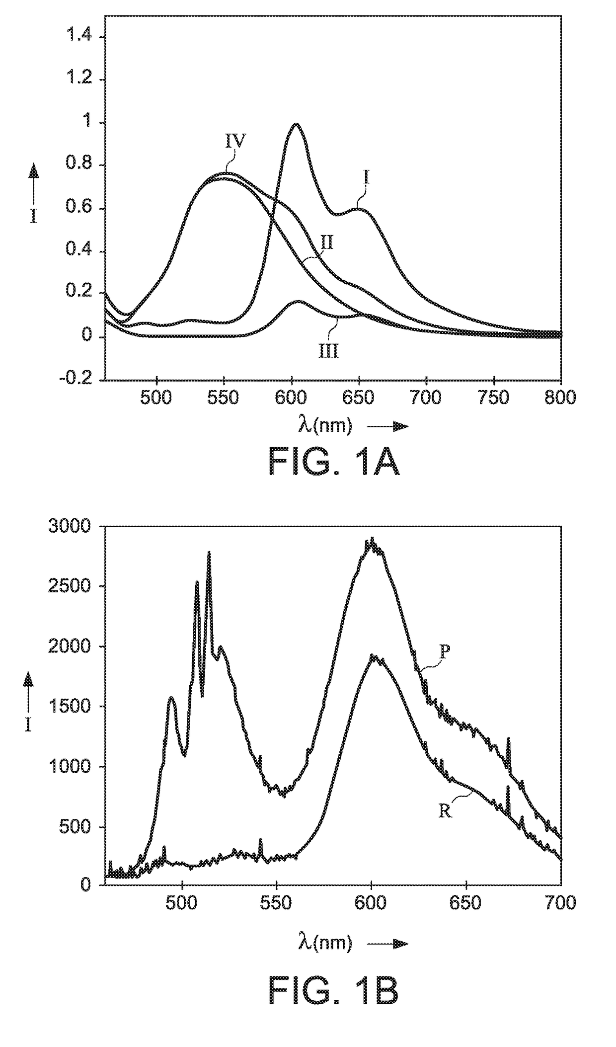
[0070]FIGS. 1A and 1B show (a) emission spectra of pure donor (II), pure acceptor (III), mixed donor+acceptor (I) as well as the sum of the pure donor and pure acceptor spectra (IV). The mixed donor+acceptor spectrum is normalized and the other spectra are scaled accordingly (FIG. 1A) and (b) Emission spectra of the mix shown in (a) on glass as reference (R (reference)) and on a square plasmonic array (P (plasmonic sample)). The spectra are recorded at 0° to the angle normal for p-polarization (FIG. 1B). The x-axis displays the wavelength in nm and the y-axis the relative intensity in counts.

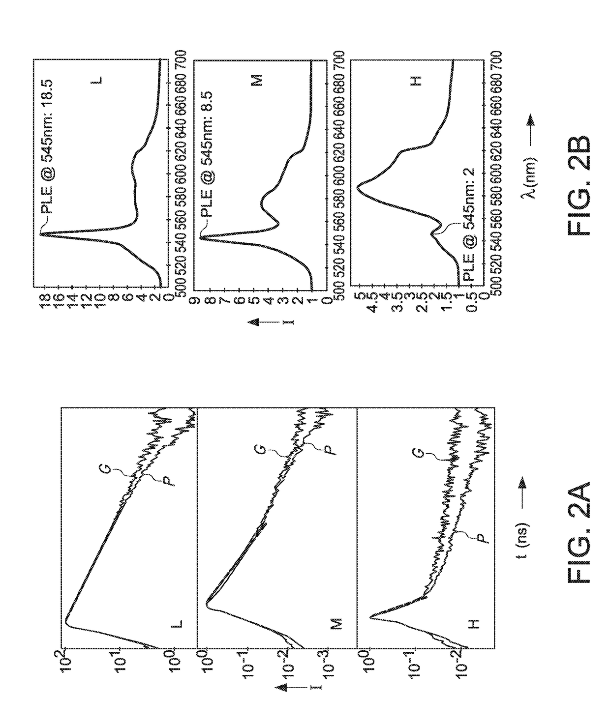
[0071]It was found that a mixed film of donor and acceptor phosphors on top of a square plasmonic nanoparticle array, the FRET rate and efficiency were almost not influenced by the plasmonics. This can be seen in the non-changing short donor decay in the mix on glass-reference as well as on plasmonics at a particular acceptor concentration, highlighted by the red dashed line in each of the three...


PUM

PropertyMeasurementUnit
wavelengthaaaaaaaaaa
heightaaaaaaaaaa

Abstract

The invention provides a lighting device comprising a light source and a light converter, wherein the light source is configured to provide light source light, wherein the light converter comprises a donor luminescent material able to convert at least part of the first light source light into donor light, and a acceptor luminescent material, wherein the donor luminescent material and acceptor luminescent material are configured as donor-acceptor luminescent materials which, upon excitation of the donor luminescent material by the light source light provide acceptor light having an acceptor light spectral distribution different from a donor light spectral distribution of the donor light, wherein the light converter further comprises a periodic plasmonic antenna array configured to enhance generation of said donor light, and wherein the lighting device is configured to provide lighting device light comprising said donor light and said acceptor light.

Description

FIELD OF THE INVENTION[0001]The invention relates to a lighting device comprising a light source and a light converter.BACKGROUND OF THE INVENTION[0002]Solid state illumination devices based on non-radiative energy transfer are known in the art. WO2015180976, for instance, describes an illumination device comprising: a wavelength converting layer comprising a photon emitting donor configured to absorb energy to reach an excited state, and a photon emitting acceptor, an energy source configured to provide energy to the donor such that the donor reach the excited state; wherein the donor and the acceptor are selected and arranged at a distance from each other such that non-radiative transfer of excitation energy from the donor to the acceptor occur, and wherein the acceptor is configured to emit a photon at a second wavelength after the transfer of energy; the illumination device further comprising a periodic plasmonic antenna array, arranged on the substrate and embedded within the w...

Claims


Application Information

Patent Timeline
Patent Type & Authority Applications(United States)
IPC IPC(8): F21K9/64G02B5/00C09K11/08F21V9/16H01L33/58H01L33/50
CPCF21K9/64F21V9/16H01L33/58H01L33/502C09K11/0883G02B5/008H01L33/504F21V9/30Y02B20/00
Inventor LUNZ, MANUELAVERSCHUUREN, MARCUS ANTONIUSLOZANO, GABRIELGUO, KEDE BOER, DIRK KORNELIS GERHARDUS
Owner SIGNIFY HLDG BV
Why Eureka
Try Eureka