
Tubular elements for cake filtration and method of providing a filtration cake

Active Publication Date: 2017-12-14
GRUNDFOS HLDG
View PDF8 Cites 0 Cited by
  • Summary
  • Abstract
  • Description
  • Claims
  • Application Information

AI Technical Summary

Benefits of technology

The present invention relates to a system that uses cake filtration to improve the quality of wastewater treatment in a plant. By using this method, the filtrate has a lower loading of organics and nutrient, which reduces the energy demand on downstream treatment facilities and increases treatment capacity. The filtration cake made from biological material can also be used as a rich fuel to increase biogas production. Additionally, positioning the cake filtration device downstream of the biological treatment facility improves the quality of secondary effluent and enables higher loads to secondary clarifiers, further increasing treatment capacity. Overall, this invention provides a more efficient and effective wastewater treatment solution with reduced energy consumption and increased production of renewable energy.

Problems solved by technology

However, although it could be seen as attractive to divert the biological material from the aerobic processing tank to a digester (in which the biological material is converted into biogas), it is found that the dry matter content of the material in the aerobic processing tank is low thereby requiring some dewatering prior to digestion which result in that although being attractive, the technical problems related to dewatering renders the use of biological material for producing e.g. biogas less attractive.
While the fine screening appears to be the more attractive of the two, problems due to fouling of the filters used in the fine screening are well known but not yet solved problems leading to difficulties in implementing such a fine screening.

Method used


Image

  • Tubular elements for cake filtration and method of providing a filtration cake
  • Tubular elements for cake filtration and method of providing a filtration cake
  • Tubular elements for cake filtration and method of providing a filtration cake

Examples


Embodiment Construction

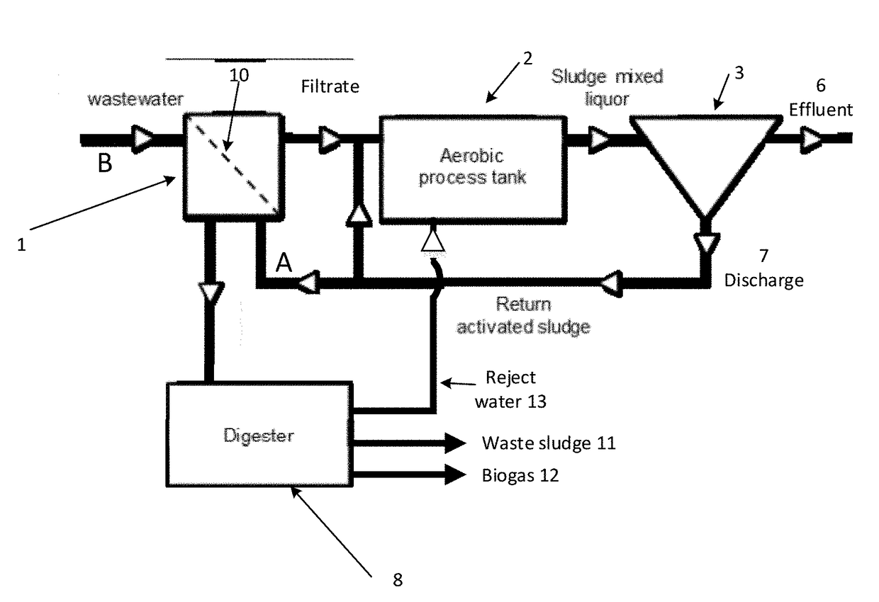
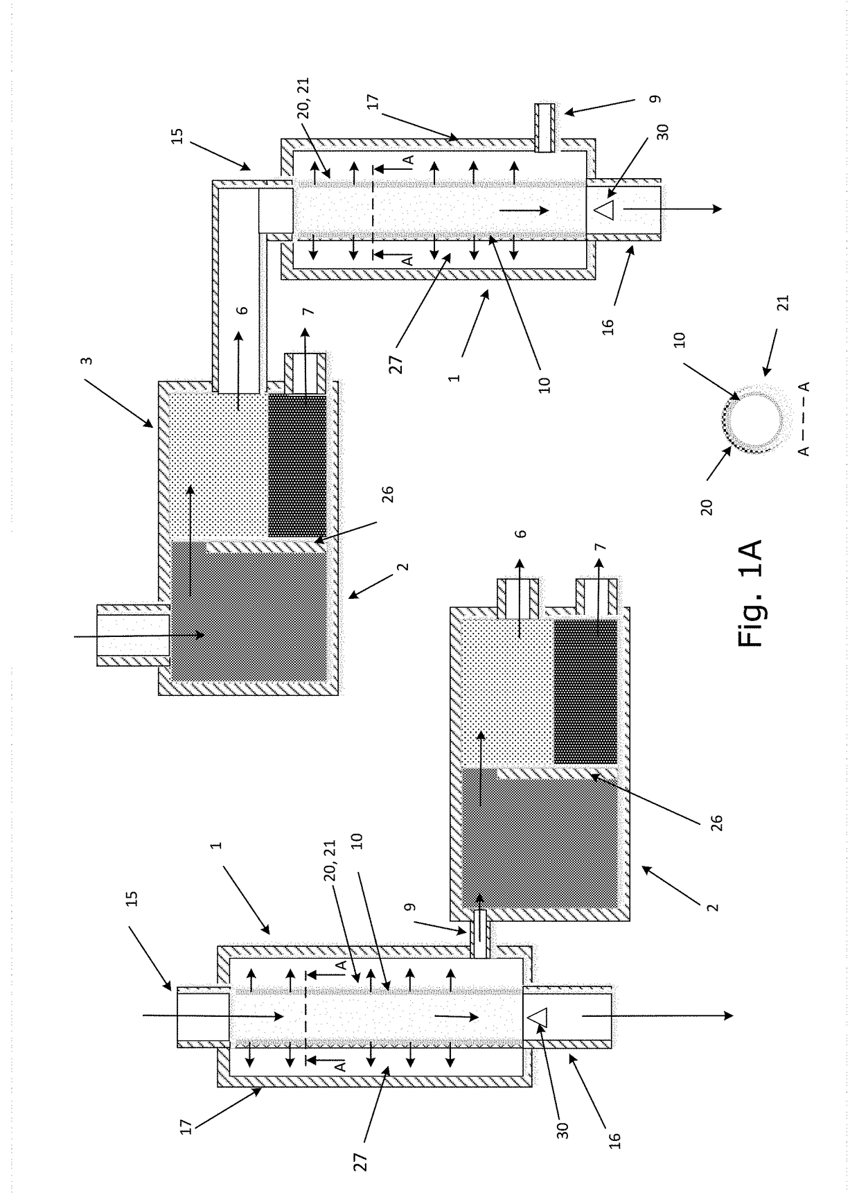
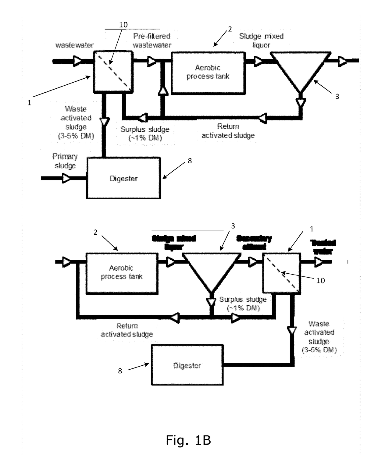
[0094]Reference is made to FIG. 1 which is a schematical illustration of a water treatment system in which a filtering device 1 according to a first embodiment of the invention is implemented. The water treatment system comprises a filtering device 1 receiving a liquid to be filtered and provides a filtrate. As disclosed in FIG. 1, the liquid to be filtered may be wastewater (not yet being biological treated) and it may be secondary effluent (supernatant of sludge mixed liquor) produced in a biological treatment device 2 (also containing a separation step).

[0095]A water treatment system in which a filtering device 1 according to the present invention may be used, may typically comprise as disclosed in FIG. 1 a biological treatment device 2 adapted to provide a sludge from wastewater or filtrated wastewater, and the biological treatment device 2 being fluidic connectable to or in fluidic connection with the filtering device 1 for receiving filtrated wastewater from the filtering devi...


PUM


Abstract

The present invention relates to a filtering device for a water treatment system comprising a biological treatment device adapted to provide a sludge from wastewater or filtrated wastewater, and / or the biological treatment device being fluidic connectable to or in fluidic connection with the filtering device for receiving filtrated wastewater from the filtering device and for delivering sludge to the filtering device. The filtering device is a cake filtration device comprising a fluid penetrable support structure and the support structure is provided as one or more tubular elements having a filtration cake provided on the inside of the fluid penetrable support structure. The filtering has device an inlet being connectable to receive liquid to be filtered so that the flux of liquid to be filtered is from the inside of the support structure, through the filtration cake and to the outside of the support structure thereby providing a filtrate, an outlet for outletting liquid from the interior of the tubular element, and a filtrate outlet for outletting filtrate from the filtering device. The filtration cake is being provided by deposition of solids from the sludge formed in the biological treatment device.

Description

FIELD OF THE INVENTION[0001]The present invention relates to a filtering device for a water treatment system comprising a biological treatment device adapted to provide a sludge from, water, such as wastewater or filtrated water, such as wastewater, and / or the biological treatment device being fluidic connectable to or in fluidic connection with the filtering device for receiving filtrated water from the filtering device and for delivering sludge to the filtering device. The filtering device is a cake filtration device comprising a fluid penetrable support structure and the support structure is provided as one or more tubular elements having a filtration cake provided on the inside of the fluid penetrable support structure. The filtering device has an inlet being connectable to receive liquid to be filtered so that the flux of liquid to be filtered is from the inside of the support structure, through the filtration cake and to the outside of the support structure thereby providing a...

Claims


Application Information

Patent Timeline
IPC IPC(8): C02F3/12C02F3/30C02F3/06C02F3/10C02F3/00C02F101/30
CPCC02F3/1221C02F3/302C02F3/006C02F3/109C02F3/06C02F3/1215C02F2203/006C02F2209/001C02F2209/03C02F2303/10C02F2303/20C02F2101/30Y02W10/10Y02W10/30
Inventor J.AE BUTTED.GER, TOMDOMINIAK, DOMINIK MAREKGAUSMANN, MARCEL
Owner GRUNDFOS HLDG
Learn More