Method and apparatus of calibrating impedance-matching current sensor

a current sensor and impedance matching technology, applied in the field of methods and apparatus of calibrating current sensors, can solve problems such as unreliability and instability, inability to effectively detect the variation of output capacitors, and inability to adjust the output voltage.

Active Publication Date: 2017-12-28
NAT CHENG KUNG UNIV
View PDF5 Cites 5 Cited by
  • Summary
  • Abstract
  • Description
  • Claims
  • Application Information

AI Technical Summary

Benefits of technology

[0016]The IMCS effectively detects the variation of the output capacitor after calibration thereof by tuning the three sensing parameters of the IMCS. Accordingly, it is to significantly overcome problems of unreliability and instability of the DC-to-DC conversion system caused by temperature, aging, DC bias variation, or parasitic effect and to maintain correct sensed results of the IMCS in transient response optimization.

Problems solved by technology

However, the output capacitor CO is varied due to different manufacturing processes, bias voltages, frequencies, and so on, resulting in incorrect current sensing.
Therefore, the incorrect sensed results of the CCS 90 cause problems of unreliability and instability and a lack of transient response optimization.

Method used


Image

  • Method and apparatus of calibrating impedance-matching current sensor
  • Method and apparatus of calibrating impedance-matching current sensor
  • Method and apparatus of calibrating impedance-matching current sensor

Examples


Embodiment Construction

[0041]Reference will now be made to the drawing figures to describe the present disclosure in detail.

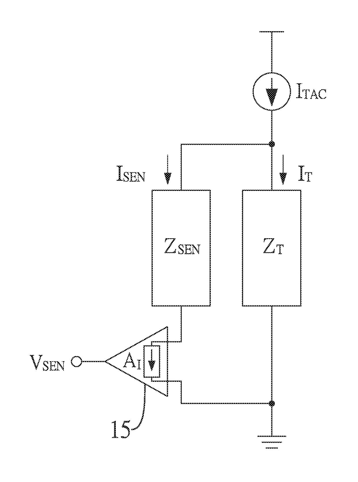
[0042]FIG. 1 shows a schematic of calibrating an impedance-matching current sensor (IMCS) of the present disclosure. The IMCS with a sense impedance ZSEN is connected in parallel to a device under test (DUT) and an equivalent impedance of the DUT is expressed as a target impedance ZT. It is assumed that the sense impedance ZSEN is equal to KI times of the target impedance ZT, i.e., ZSEN=KI×ZT.

[0043]In addition, an alternating-current (AC) test current ITAC is provided, and a part of the AC test current ITAC, i.e., a target current IT, flows through the DUT and the other part of the AC test current ITAC, i.e., a sense current ISEN flows through the IMCS. Therefore, under a certain frequency f0, the following relationship is satisfied:

ZSEN(f0)=KI×ZT(f0)

[0044]Correspondingly, a relationship between the target current IT and the sense current ISEN under the certain frequency f0 is satisf...


PUM


Abstract

A method of calibrating an impedance-matching current sensor (IMCS) is provided. The IMCS has an equivalent sensing impedance and is connected in parallel to an object under test. The method includes steps of: using an alternating-current (AC) current source to provide a first AC current flowing through the object under test and provide a second AC current flowing through the IMCS; designing the equivalent sensing impedance to make the first AC current much greater than the second AC current; proportionally converting the second AC current into a sense voltage; and adjusting a magnitude of the sense voltage to be proportional to a magnitude of the first AC current. Accordingly, it is to significantly overcome problems of unreliability and instability of the DC-to-DC conversion system caused by temperature, aging, DC bias variation, or parasitic effect, thus maintaining correct sensed results of the current sensor in transient response optimization.

Description

BACKGROUND1. Technical Field[0001]The present disclosure relates generally to a method and an apparatus of calibrating a current sensor, and more particularly to a method and an apparatus of calibrating an impedance-matching current sensor.2. Description of Related Art[0002]Switching buck converters are widely used as voltage regulators in battery-powered portable devices to achieve high power-conversion efficiency. FIG. 20 shows a block diagram of a conventional buck converter which includes a power stage 91 and a feedback controller 92. The synchronous topology of the buck converter includes a pair of switches SH, SL, an output capacitor Co, and an output inductor LO. The high-side switch SH and the low-side switch SL are both electrically connected to an input voltage VI, which is a direct current (DC) voltage at an input side of the buck converter. In this example, the high-side switch SH is, but not limited to, a P-type MOSFET switch and the low-side switch SL is, but not limit...

Claims


Application Information

Patent Timeline
Patent Type & Authority Applications(United States)
IPC IPC(8): G01R35/00H03H7/38
CPCH03H7/38G01R35/005G01R19/0092G01R31/40
Inventor FANG, KUAN-YUHUANG, SZU-YUKUO, TAI-HAUR
Owner NAT CHENG KUNG UNIV
Why Eureka
Try Eureka