
Integrated coolant bottle assembly

Active Publication Date: 2017-12-28
TESLA INC
View PDF4 Cites 17 Cited by
  • Summary
  • Abstract
  • Description
  • Claims
  • Application Information

AI Technical Summary

Benefits of technology

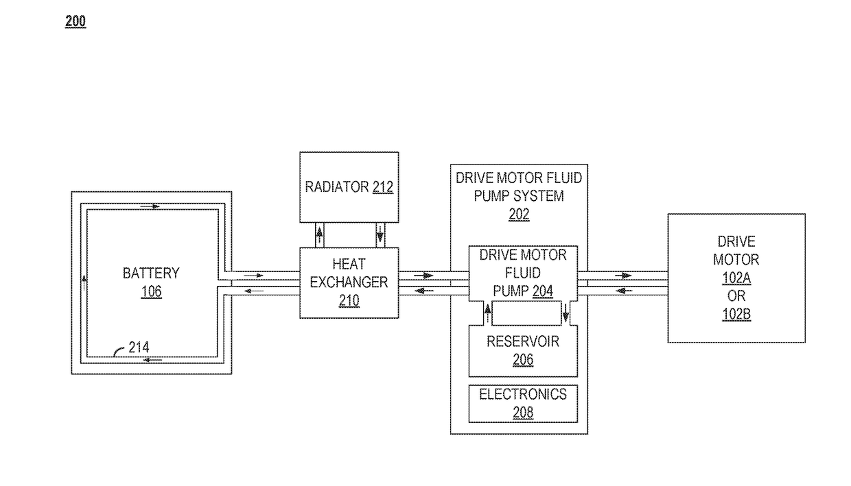
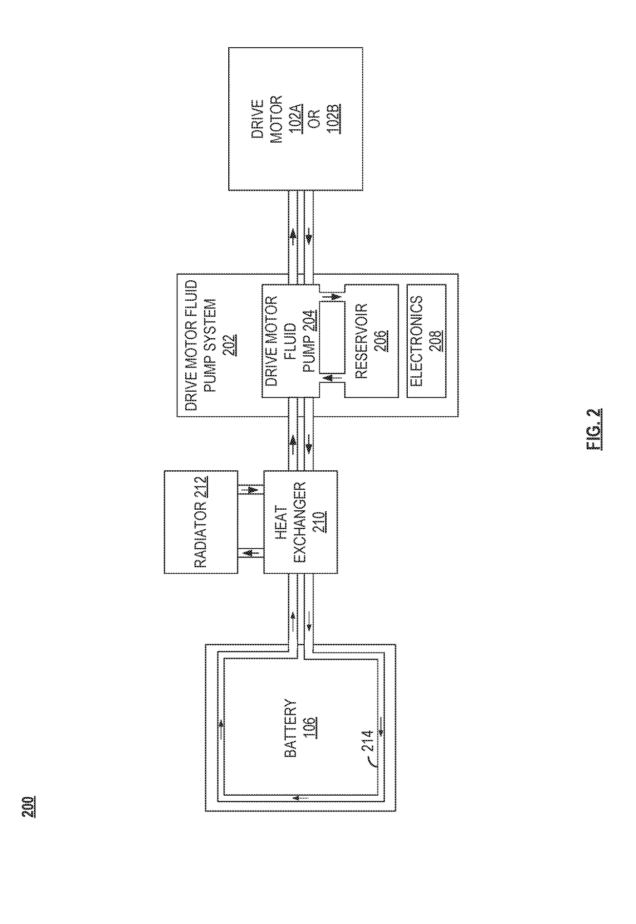
The present patent application claims priority to a provisional patent application filed in July 2016 and is about a new thermal management system for electric vehicles. The system is designed to efficiently cool the internal components of the vehicle, such as the motor, while also addressing the challenges of a wide range of ambient operating environments. The new system is designed to be more efficient, compact, and easy to assemble than previous cooling systems. It includes a new reservoir design that reduces the number of connections, hoses, and weld points, which can improve the smoothness and fluidity of the coolant flow through the system. Overall, the new system is designed to improve the cooling performance of electric vehicles while also being more efficient in its construction and assembly.

Problems solved by technology

Electric motors can generate considerable heat, especially in the traction motor of a vehicle where size and weight constraints are coupled with the need for high power output.
Electric motor overheating causes the motor winding insulation to deteriorate quickly.
Another issue caused by overheating is that permanent magnets in the rotor lose their magnetic properties as they overheat, resulting in a loss of efficiency.
For induction motors, an increase in temperature of the copper windings reduces efficiency of the induction motorcopper electrical resistivity increases 4% for every 10-degree Celsius temperature increase.
Such a prior art implementation provides a significant number of connections, hosing, fasteners, etc. and also provides a large number of possible failure points within the overall thermal system.
In addition, such a prior art implementation can be very time-consuming and labor-intensive when assembling a vehicle that includes such a prior art thermal system.
The multi-faceted construction and assembly of these parts is time-intensive and gives rise to multiple points of potential failure in hoses, clamps, electrical connections, etc.
Furthermore, the need to weld the typical coolant bottle housing portions often necessitates multiple weld points along the inlet and outlet channels of the structure, such that the weld lines and residue from the welding process are introduced into the flow channels of the inlets and outlets, compromising the smoothness and fluidity of the channel and reducing efficiency of liquid flow through the channel.

Method used


Image

  • Integrated coolant bottle assembly
  • Integrated coolant bottle assembly
  • Integrated coolant bottle assembly

Examples


Embodiment Construction

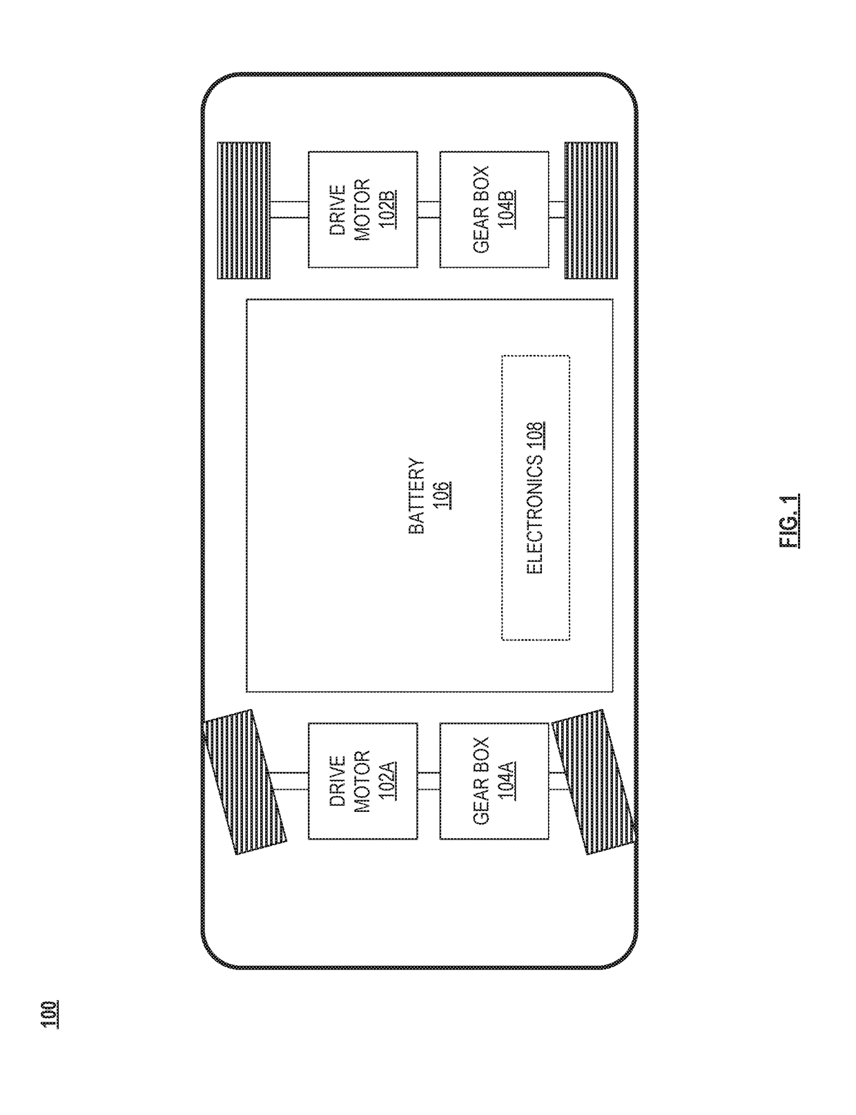
[0024]FIG. 1 illustrates an example 100 of basic components of a battery powered electric vehicle (electric vehicle). The electric vehicle includes at least one drive motor (traction motor) 102A and / or 102B, at least one gear box 104A and / or 104B coupled to a corresponding drive motor 102A and / or 102B, a battery 106 and electronics 108. Generally, the battery 106 provides electricity to the power electronics of the electric vehicle and to propel the electric vehicle using the drive motor 102A and / or 102B. The electric vehicle includes a large number of other components that are not described herein but known to one of ordinary skill. While the construct of the electric vehicle of FIG. 1 is shown to have four wheels, differing electric vehicles may have fewer or more than four wheels. Further, differing types of electric vehicles may incorporate the inventive concepts described herein, including motor cycles, aircraft, trucks, boats, train engines, among other types of vehicles.

[0025...


PUM


Abstract

An integrated coolant bottle assembly includes a reservoir configured for use in a thermal system. Examples of such thermal systems include a cooling / heating system of a battery powered electric vehicle, electric power generators (e.g., motor-based systems), other physical plant installations, etc. Such a reservoir includes a first section and a second section. The second section is joined to the first section at a reservoir interface thereby forming the reservoir that is configured for storage and / or flow of a liquid medium. The first section may include an integrated channel that provides a pathway for the flow of the liquid medium. The reservoir may also include a component interface configured to facilitate connection of a component thereto (e.g., a pump, a battery pump, a powertrain pump, a chiller, a heater, a filter, an aerator, a valve, a connector, a fan, or a radiator).

Description

CROSS REFERENCE TO RELATED PATENTS / PATENT APPLICATIONS[0001]The present U.S. Utility patent application claims priority pursuant to 35 U.S.C. §119(e) to U.S. Provisional App. Ser. No. 62 / 353,763, entitled “INTEGRATED COOLANT BOTTLE ASSEMBLY,” filed Jun. 23, 2016, which is hereby incorporated herein by reference in its entirety and made part of the present U.S. Utility patent application for all purposes.BACKGROUNDTechnical Field[0002]The present disclosure relates generally to thermal management systems; and, more particularly, to thermal management systems such as those that may be implemented within vehicles.Description of Related Art[0003]Electric motors can generate considerable heat, especially in the traction motor of a vehicle where size and weight constraints are coupled with the need for high power output. Electric motor overheating causes the motor winding insulation to deteriorate quickly. For every 10-degree Celsius rise in electric motor temperature, insulation life is ...

Claims


Application Information

Patent Timeline
IPC IPC(8): H01M10/613H01M10/63H01M10/6567
CPCH01M10/613H01M2220/20H01M10/63H01M10/6567B60K11/02B60K2001/003B60K2001/008Y02T10/70Y02E60/10B60L58/27B60L1/003B60L2200/36B60L2200/32B60L2200/24B60L2200/10B60Y2200/91
Inventor KRULL, JUSTIN THOMASPINTO, PREM MARK
Owner TESLA INC
Learn More