
Charging member, process cartridge and electrophotographic apparatus

Active Publication Date: 2018-01-25
CANON KK
View PDF4 Cites 8 Cited by
  • Summary
  • Abstract
  • Description
  • Claims
  • Application Information

AI Technical Summary

Benefits of technology

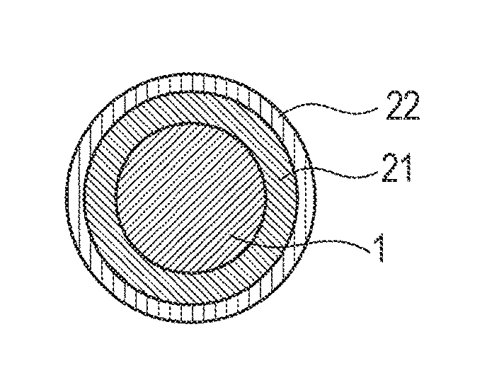
The present invention provides a charging member that can prevent uneven abrasion of a photosensitive member and staining on the surface of the charging member, which can improve the quality of image formed by an electrophotographic apparatus. It also provides a process cartridge and an electrophotographic apparatus that can contribute to forming a high-quality electrophotographic image.

Problems solved by technology

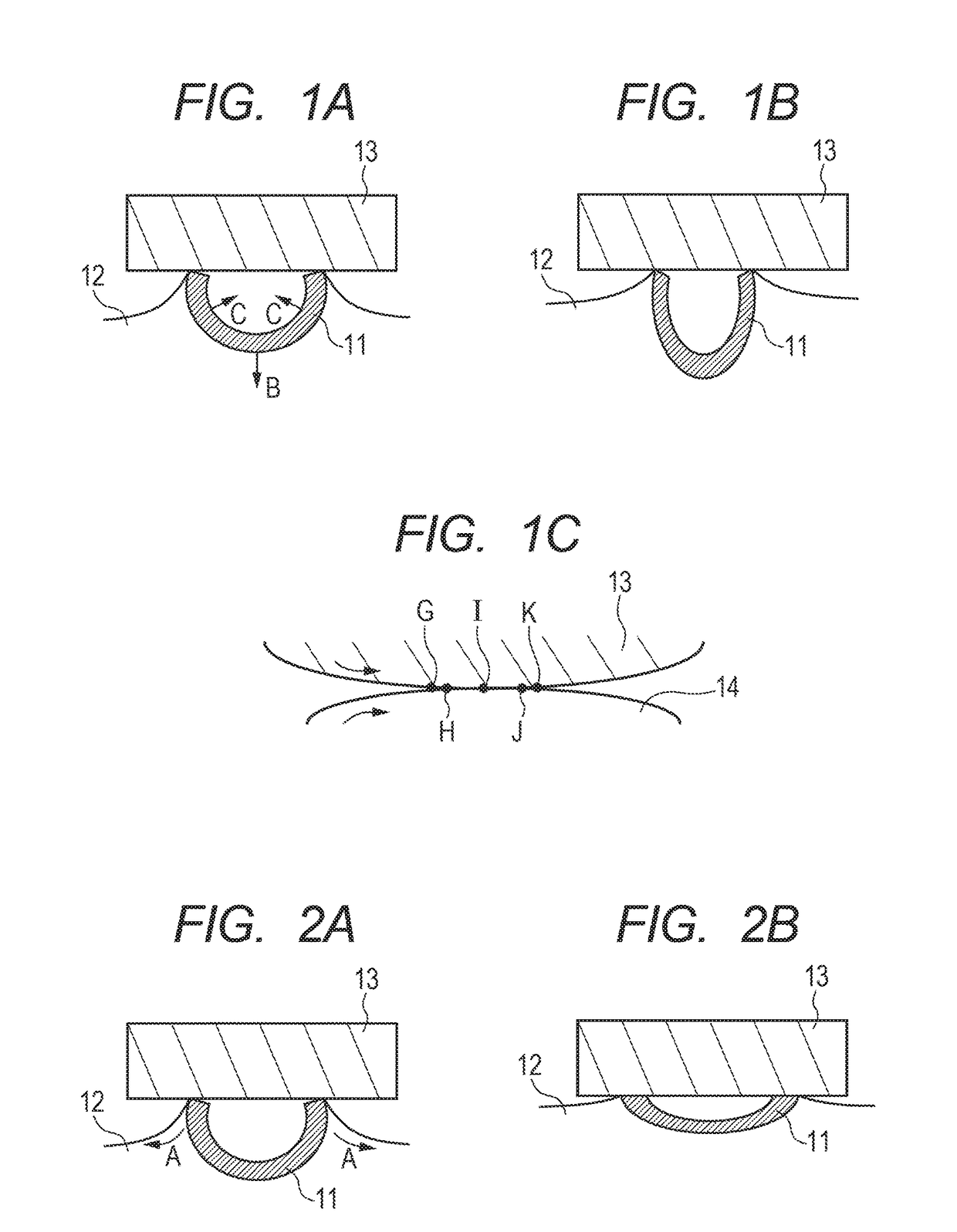
However, when the charging member described in Patent Literature 1 comes into contact with a photosensitive member, the contact pressure concentrates on the protrusion derived from the resin particle on the surface of the charging member (charging roller), and as a result, non-uniform abrasion occurs on the surface of the photosensitive member in a long-term use, which may cause a vertically streaked image defect due to the non-uniform abrasion.

Method used


Image

  • Charging member, process cartridge and electrophotographic apparatus
  • Charging member, process cartridge and electrophotographic apparatus
  • Charging member, process cartridge and electrophotographic apparatus

Examples


production example 1

Particle No. 1

[0111]An aqueous mixed solution was prepared containing 4000 parts by mass of ion-exchanged water, 9 parts by mass of colloidal silica as a dispersion stabilizer and 0.15 parts by mass of polyvinylpyrrolidone. Then, an oily mixed solution was prepared containing 50 parts by mass of acrylonitrile, 45 parts by mass of methacrylonitrile and 5 parts by mass of methyl acrylate as polymerizable monomers, and 12.5 parts by mass of n-hexane as an included substance, and 0.75 parts by mass of dicumyl peroxide as a polymerization initiator. This oily mixed solution was added to the aqueous mixed solution and 0.4 parts by mass of sodium hydroxide was further added thereto to prepare a dispersion.

[0112]The obtained dispersion was stirred to mix together with a homogenizer for 3 minutes, charged into a polymerization reactor which had been purged with nitrogen, and reacted at 60° C. for 20 hours while stirring at 400 rpm to prepare a reaction product. The obtained reaction product ...

production example 2

Particle No. 2

[0113]A resin particle No. 2 was produced with the same method as in Production Example 1 except that classifying conditions were changed. The physical properties of the resin particle No. 2 are shown in Table 1.

Production Examples 3 to 8: Production of Resin Particle's Nos. 3 to 8

[0114]Resin particles were produced with the same method as in Production Example 1 except that one or more of the amount of colloidal silica used, the type and amount of a polymerizable monomer used, and the rotational frequency for stirring in polymerization Were changed, and classified to obtain resin particles Nos. 3 to 8, respectively. The physical properties of the respective resin particles are shown in Table 1.

TABLE 1Amount ofRotationalResinResincolloidal silicaPolymerizable monomerfrequencyparticleProductionparticleused [parts byand amount thereof usedfor stirringdiameterExampleNomass][parts by mass][rpm][μm]119Acrylonitrile 50-40030methacrylonitrile 45-methyl acrylate 5229Acrylonitr...

production example 11

or Measuring Gas Permeability No. 1

[0117]The sheet in this Production Example is a sheet for measuring the gas permeability of a resin material obtained by removing an included substance from a resin particle. The resin particle 1 was heated and decompressed at 100° C. for removing the included substance to obtain a resin composition. Thereafter, a metal mold (φ 70 mm, 500 μm in depth) heated to 160° C. was filled with the resin composition, and pressurized at a pressure of 10 MPa to obtain a circular sheet for measuring gas permeability 1 having a diameter of 70 mm and a thickness of 500 μm.

Production Examples 12 to 16: Production of Sheets for Measuring Gas Permeability Nos. 2 to 6

[0118]Sheets for measuring gas permeability Nos. 2 to 6 were obtained with the same method as in the above using the resin particles Nos. 4 to 8, respectively, in place of the resin particle No. 1.

[0119]Using each of the sheets for measuring gas permeability No. 1 to 6, the oxygen gas permeability was me...


PUM


Abstract

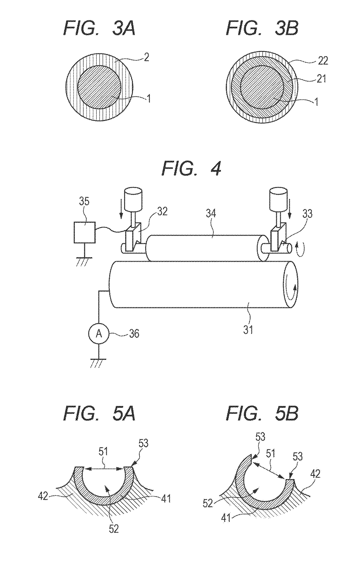
Provided is a charging member capable of suppressing the occurrence of an image defect due to the non-uniform abrasion of a photosensitive member and a stain, in a long-term use.The charging member includes an electro-conductive elastic layer as a surface layer.The electro-conductive elastic layer contains a binder and a bowl-shaped resin particle having an opening. The surface of the charging member has a concavity and a protrusion derived from the bowl-shaped resin particle. The relations represented by the following formulae are satisfied,0.2≤S=S5-S1S1≤0.50.15≤d=d5-d1d1≤0.5wherein, when the charging member is pressed onto a glass plate with 100 (g) load, S1 is the average value of contact areas, dl is the average value of heights of spaces formed in a contact region; and when the load is changed to 500 (g), S5 is the average value of contact areas, d5 is the average value of heights of spaces.

Description

TECHNICAL FIELD[0001]The present invention relates to a charging member to charge the surface of an electrophotographic photosensitive member as a member to be charged to a predetermined electrical potential by applying a voltage, and a process cartridge and an electrophotographic image-forming apparatus (hereinafter, referred to as an “electrophotographic apparatus”) using the same.BACKGROUND ART[0002]An electrophotographic apparatus employing an electrophotographic method primarily includes an electrophotographic photosensitive member (hereinafter; also simply referred to as “photosensitive member”), a charging device, an exposing device, a developing device, a transfer device and a fixing device. As the charging device, a contact charging device which charges the surface of a photosensitive member by applying a voltage (a voltage of a DC voltage only or a voltage of a DC voltage superimposed with an AC voltage) to the charging member brought into contact with or closely disposed ...

Claims


Application Information

Patent Timeline
IPC IPC(8): G03G15/02
CPCG03G15/0233
Inventor UEMATSU, ATSUSHITANIGUCHI, TOMOHITOWATANABE, MASAHIROMIYAGAWA, NOBORUSATO, TAICHIAOYAMA, TAKEHIKO
Owner CANON KK
Learn More