System and method for dewatering coal combustion residuals

a technology of coal combustion and dewatering system, which is applied in the direction of drying solid materials, drying, lighting and heating apparatus, etc., can solve the problems of reducing the volume of the water tank, so as to facilitate the removal of water and reduce the volume

Active Publication Date: 2018-02-01
AECOM TECHNICAL SERVICES INC
View PDF21 Cites 14 Cited by
  • Summary
  • Abstract
  • Description
  • Claims
  • Application Information

AI Technical Summary

Benefits of technology

[0008]A method and system for dewatering and consolidating coal combustion residuals (CCR) (or coal combustion products (CCP)) such as fly ash, bottom ash, pyrites, flue gas desulfurization sludge, etc., that uses horizontal drains installed in a CCR pond before, during or after the CCR is added to the pond. The horizontal drains may be installed below the surface of the CCR or on the surface of existing CCR to which additional CCR material is added. The drains may be connected to a vacuum pump via collector hoses or pipe, and a collection header pipe. The vacuum pump operation facilitates the removal of water from the CCR, consolidates the settled material and reduces its volume, enabling continued discharge of dredged CCR or disposal of the material by removal and landfilling or capping (i.e., closing the material in place).
[0009]In some embodiments, imparting vibrational energy to the surface layers of the CCR will improve compaction of the CCR to provide additional strength to the CCR for supporting earth working equipment that may be required to be driven on the surface of the pond for the purpose of closing it. Vibrational energy may be supplied by transporting or hauling compaction equipment or driving vehicle-based equipment across the surface. Successive installation of horizontal drains within accumulating CCR and consolidation by vacuum pumping may continue until the disposal pond is filled with consolidated CCR. In the case of closing the pond in place, vacuum pumping may be continued for some period after final cover installation to enhance containment performance by over-consolidation. The horizontal drain system may also be used to deliver liquid reagents for sediment treatment or to circulate water for flushing. The method enables the disposal pond to be on land or under water below the original sediment line.
[0010]Additionally in some embodiments, the prefabricated drains may be laid out on a surface of ground or other CCR and a suitably graded 3-inch to 4-foot thick layer of bottom ash, fly ash, sand or larger-diameter-solid particles may be added on top of the horizontal prefabricated drains. This can be achieved via mechanical placement or dredging the material from a nearby pond over the drains. Large diameter solid particles will inherently settle atop the drains as the material is placed over the drains as the large particles are more mobile in gravity settling. In this manner, finer CCR may be more efficiently dewatered using the above described method of vacuum consolidation dewatering. This layer of ash or sand over the prefabricated drains filters the water and allows it to flow through without carrying the very fine particles of CCR to the surface of the prefabricated drains themselves. The finer particles may have a tendency to plug off the prefabricated drain geotextile covering, oftentimes referred to as the filter jacket, and the layer of suitably graded ash or sand prevents that from happening.

Problems solved by technology

CCR is known to be unstable when saturated.
When saturated CCR is subject to shear strain, it densifies and expels water, resulting in a near total loss of shear strength.
This process may result in overtopping of impoundments and makes excavation and handling difficult to impossible.
Often, the filtered CCR cake requires solidification / stabilization because it cannot support earthwork equipment that is used on the surface of landfills.
Since CCR does not allow water to flow out easily due to its very low hydraulic conductivity, drainage pathways are provided in the CCR volume to accelerate consolidation.

Method used


Image

  • System and method for dewatering coal combustion residuals
  • System and method for dewatering coal combustion residuals
  • System and method for dewatering coal combustion residuals

Examples


Embodiment Construction

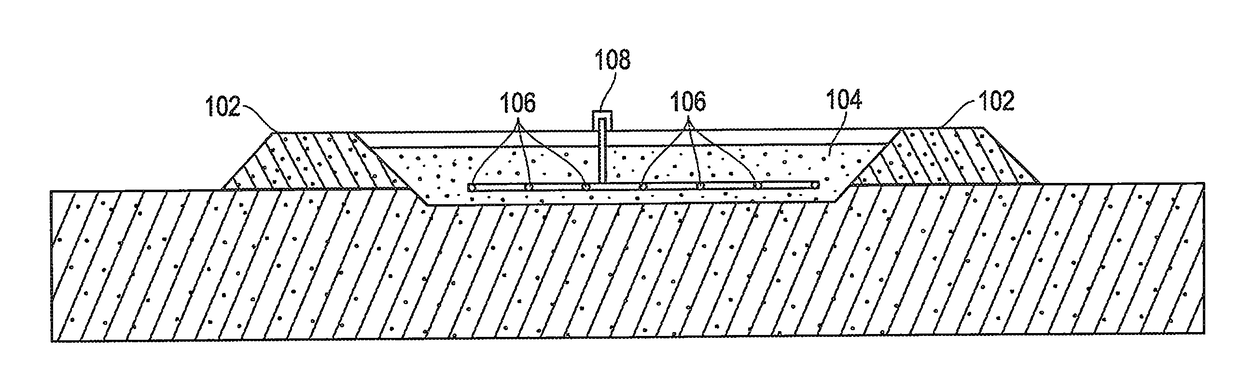
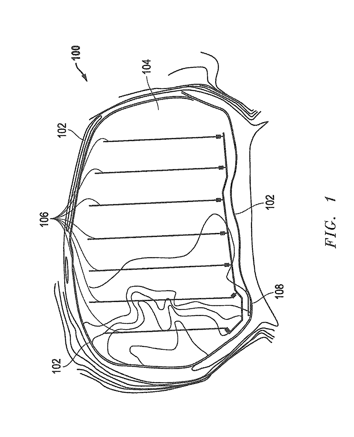
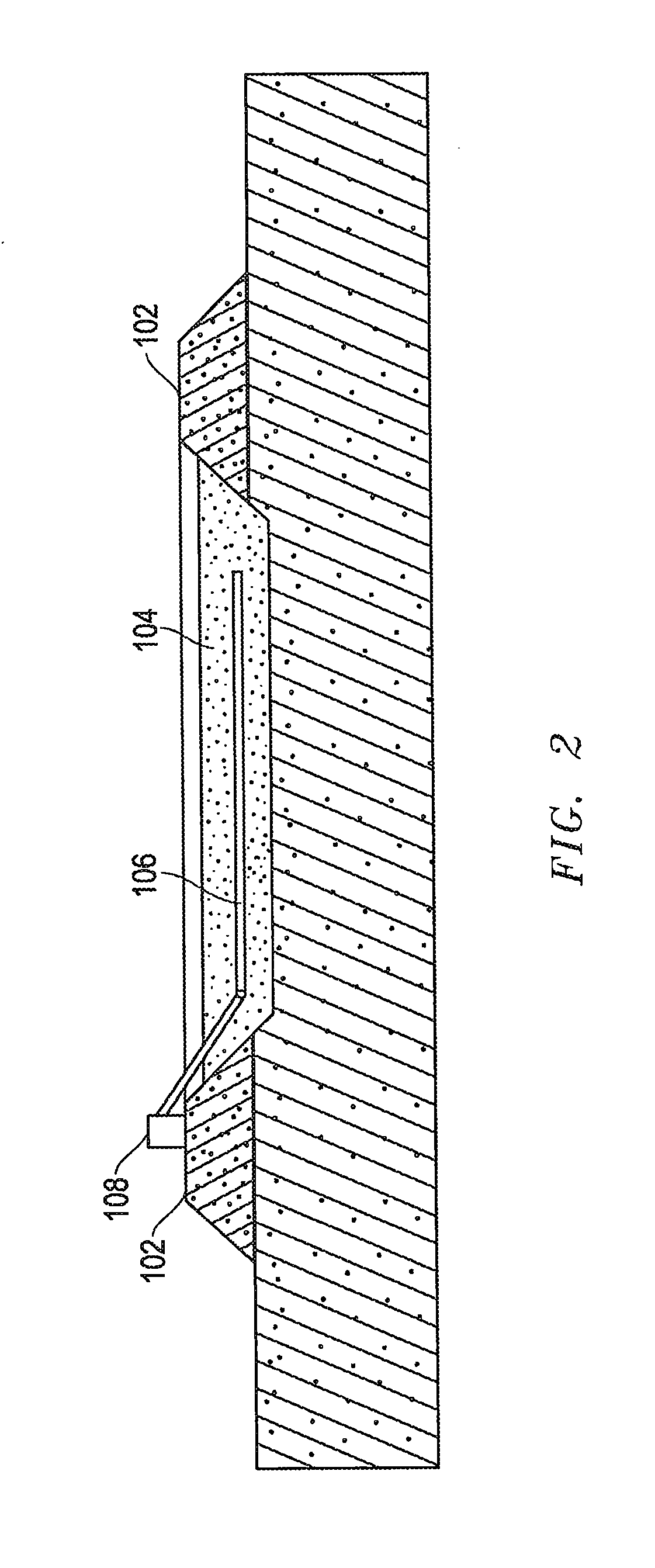
[0019]The present invention is directed to improved methods and systems for, among other things, system and method for dewatering coal combustion residuals. The configuration and use of the presently preferred embodiments are discussed in detail below. It should be appreciated, however, that the present invention provides many applicable inventive concepts that can be embodied in a wide variety of contexts other than system and method for dewatering coal combustion residuals. Accordingly, the specific embodiments discussed are merely illustrative of specific ways to make and use the invention, and do not limit the scope of the invention.

[0020]Embodiments of the present invention include the installation of prefabricated drains in a horizontal, generally co-planar pattern below the surface of the CCR and putting suction or a vacuum on the horizontal drains to withdraw water from the CCR material to lower the water level down to the level of the prefabricated drains below the CCR surf...


PUM

PropertyMeasurementUnit
depthaaaaaaaaaa
thickaaaaaaaaaa
thickaaaaaaaaaa

Abstract

The installation of prefabricated drains in a horizontal, generally co-planar pattern below the surface of the CCR with suction or a vacuum to withdraw water from the CCR material to lower the water level down to the level of the prefabricated drains below the CCR surface. Dewatering may be coupled with imparting vibrations to the material to further promote both additional dewatering and compaction of the CCR material in the pond. A suitably graded bottom ash, fly ash, sand or large-diameter-solid particle layer may be added on top of the horizontal drains to enhance dewatering of finer CCR material.

Description

PRIORITY STATEMENT UNDER 35 U.S.C. §119 & 37 C.F.R. §1.78[0001]This non-provisional application claims priority based upon prior U.S. patent application Ser. No. 62 / 368,029 filed Jul. 28, 2016, in the names of Steven Kosler, David Seeger, and G. Richard Bird entitled “SYSTEM AND METHOD FOR DEWATERING COAL COMBUSTION RESIDUALS”, the disclosures of which are incorporated herein in their entirety by reference as if fully set forth herein.FIELD OF INVENTION[0002]This invention relates to closure of coal combustion residuals (CCR), sometimes referred to as coal combustion products (CCP), fly ash, gypsum, calcium sulfite, bottom ash, pyrites, ponds or impoundments and more specifically, a method and apparatus for dewatering and consolidating CCR to reduce its volume, water content, and / or to stabilize its physical properties for disposal, closure or reuse.BACKGROUND OF THE INVENTION[0003]Past coal-fired generation activities have resulted in CCR sediments in disposal ponds or impoundments...

Claims


Application Information

Patent Timeline
Patent Type & Authority Applications(United States)
IPC IPC(8): C10L5/04F26B5/12
CPCC10L5/04C10L2290/08F26B5/12E02D3/103
Inventor KOSLER, STEVENSEEGER, DAVIDBIRD, GEORGE RICHARD
Owner AECOM TECHNICAL SERVICES INC
Why Eureka
Try Eureka