
Method and system for magnetic resonance imaging

a magnetic resonance imaging and magnetic field technology, applied in the field of magnetic resonance imaging, can solve the problems of inability to pre-compute the activation mode, inhomogeneity of spatial data, imaging artefacts, etc., and achieve the effect of increasing the level of useable signal

Active Publication Date: 2018-02-01
UNIVERSITY OF MELBOURNE
View PDF5 Cites 1 Cited by
  • Summary
  • Abstract
  • Description
  • Claims
  • Application Information

AI Technical Summary

Benefits of technology

The present invention provides methods for magnetic resonance imaging that can be implemented without extensive real-time calculations and can be performed using a single transmit coil in MRI systems. The methods involve a pulse sequence that aims to cause a desired total rotation of the net magnetization vector of an ensemble of nuclei in the portion of the subject. The pulse sequence includes a plurality of slice-selective pulses that individually rotate the net magnetization vector by a small angle. The resulting magnetization vector is then aligned with the magnetic field and a final phase adjustment is performed to correct any de-phasing of the magnetization vectors. The methods can be used in magnetic resonance imaging to improve image quality and provide more accurate information about the nuclear magnetic moments of the subject.

Problems solved by technology

However, local magnetic and electrical field effects in the subject can lead to spatial inhomogeneity in the local radio-frequency (RF) transverse magnetic field (B1) the nuclei are exposed to.
Inhomogeneity in the B1 field is more problematic at B0 fields above 3 T and can lead to imaging artefacts which, in the worst case, are manifested as zero signal in some regions of the image.
However the manner of activation cannot be pre-computed and must be calculated in real time while the subject is positioned in the imaging device and stationary.
Moreover the calculations can take many minutes to complete, and while they are occurring the patient cannot move.

Method used


Image

  • Method and system for magnetic resonance imaging
  • Method and system for magnetic resonance imaging
  • Method and system for magnetic resonance imaging

Examples


Embodiment Construction

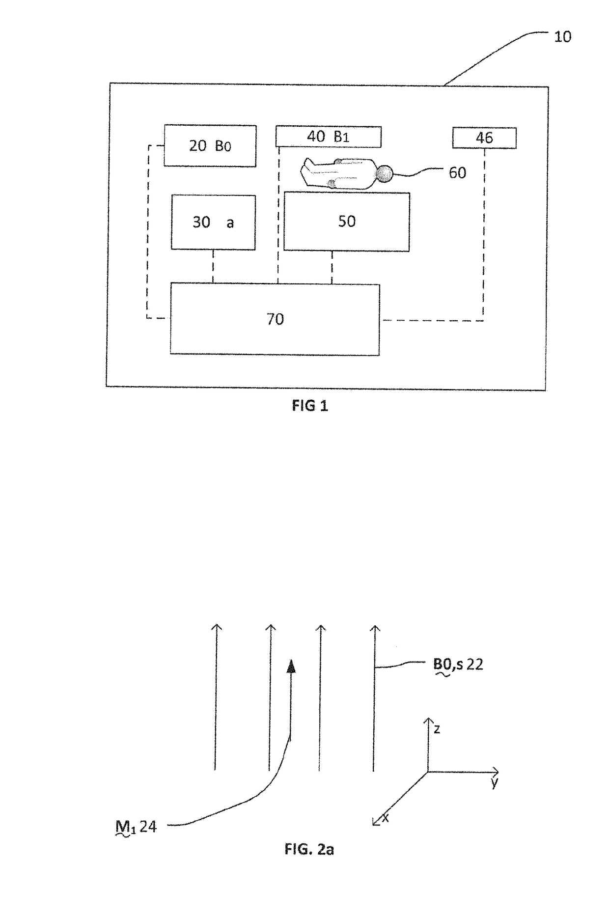
[0049]FIG. 1 shows a highly schematic block diagram for a Magnetic Resonance Imaging (MRI) system 10 including:

[0050]a magnetic field producing means 20;

[0051]a magnetic field gradient producing means 30;

[0052]a radio-frequency magnetic field generating means 40;

[0053]an RF receiver 46;

[0054]a positioning means 50; and

[0055]a control unit 70.

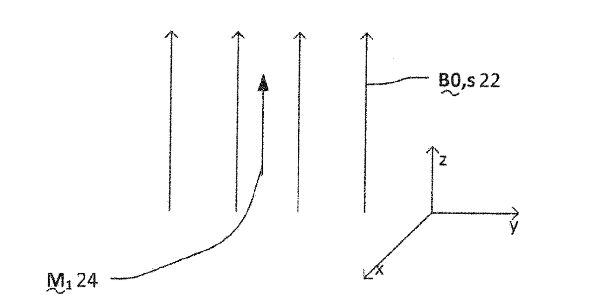
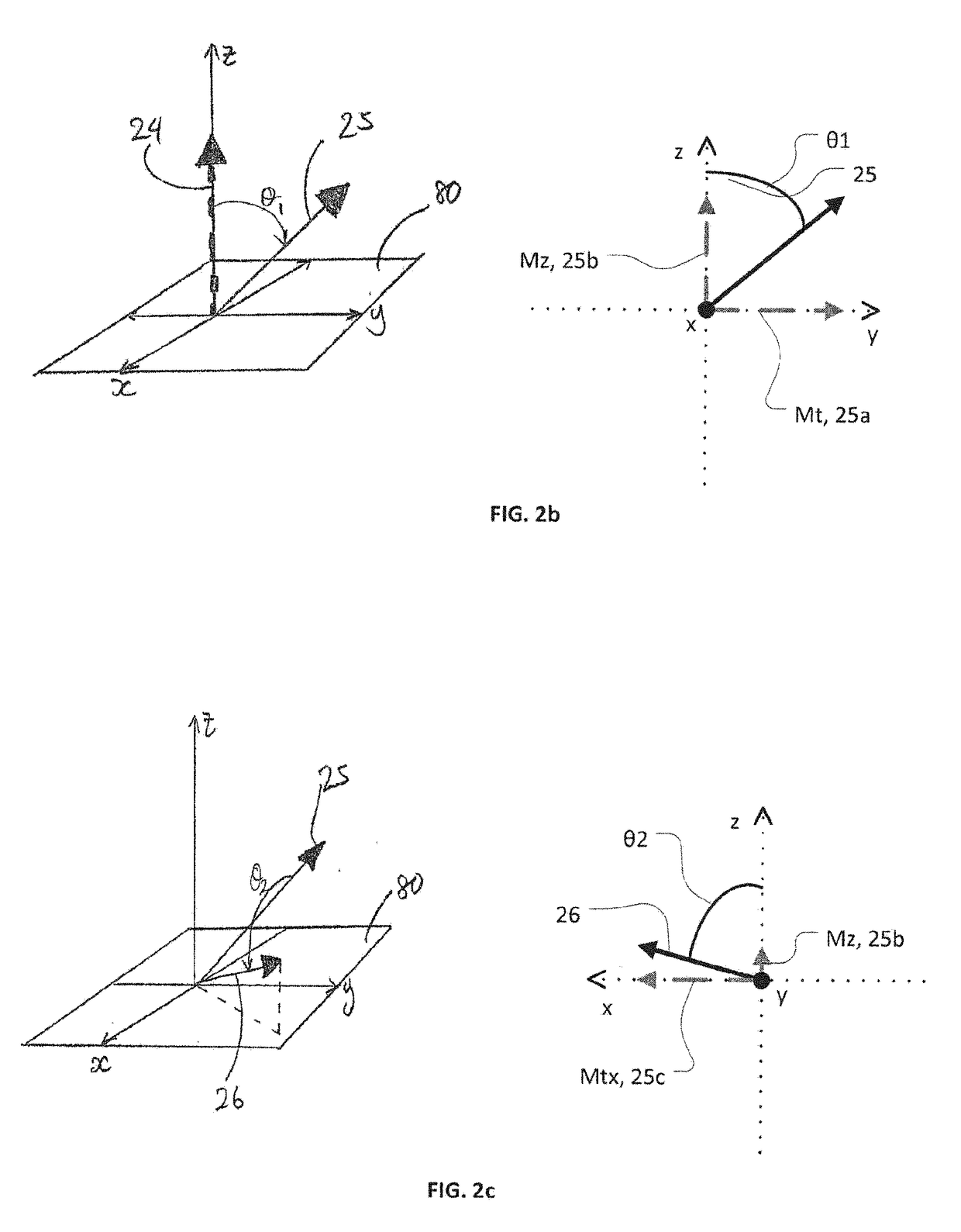
[0056]The magnetic field producing means 20 is configured to produce a static uniform magnetic field B0,s, 22 aligned to a longitudinal direction along the z-axis (FIG. 2a). A preferred example of the field producing means 20 is a superconducting magnet system.

[0057]The magnetic field gradient producing means 30 is configured to produce a magnetic field gradient G, 32. This can be thought of an additional magnetic field that alters the magnetic field B0,s to produce a modified magnetic field B0, 24. The gradient is not strong enough to vary the direction of the field, so B0 is always parallel with B0,s in the longitudinal axis. Therefore it suff...


PUM


Abstract

An MRI pulse sequence is disclosed. The pulse sequence involves a plurality of slice selective pulses (51,55) which each individually have a desired rotation that is less than or equal to the total desired rotation. The slice selective pulses each cause a rotation about respective axes, which may be different to each other. Optionally phase correction (re-phasing) gradients (53, 56) can also be included in the pulse sequence.

Description

FIELD OF THE INVENTION[0001]This invention generally relates to Magnetic Resonance Imaging. More specifically, the invention relates to radio-frequency magnetic field pulse sequences and associated magnetic field gradients.BACKGROUND OF THE INVENTION[0002]Magnetic Resonance Imaging (MRI) exploits the nuclear magnetic resonance (NMR) phenomena by combining NMR with gradient magnetic fields to allow cross-sectional slice-selective excitation of nuclei within a subject under examination. Typically, a pulse-sequence of radio-frequency magnetic fields (RF pulse) and associated magnetic field gradients is used with further two dimensional (2D) encoding of the NMR signals to create a 2D image of a portion of the subject. A 3D image of the subject can then be obtained by combining many slices together.[0003]By increasing the static magnetic field strength (B0) an improved signal-to-noise ratio may be obtained along with improved spatial resolution in the images created. Ideally, in an MR sy...

Claims


Application Information

Patent Timeline
IPC IPC(8): G01R33/483G01R33/24G01R33/565
CPCG01R33/4833G01R33/5659G01R33/24G01R33/32G01N24/12G01Q60/52
Inventor ORDIDGE, ROGER JOHN
Owner UNIVERSITY OF MELBOURNE
Learn More