
Manure agitation vessel with remote power source

Inactive Publication Date: 2018-02-08
1863385 ONTARIO INC
View PDF37 Cites 3 Cited by
  • Summary
  • Abstract
  • Description
  • Claims
  • Application Information

AI Technical Summary

Benefits of technology

The patent describes a manure agitation vessel that can be stabilized by added equipment. This added equipment includes hydraulically actuated outriggers that are attached to the frame of the vessel. The outriggers can be raised and lowered to provide extra stability during transport and use. The outriggers also have a frame for holding additional floatation. The frame is attached to the vessel frame by an outrigger arm at an outrigger hinge. This added equipment helps to ensure the manure agitation vessel operates safely and efficiently.

Problems solved by technology

Livestock produce a large amount of manure.
If the sludge layer is not periodically agitated and removed, it will eventually decrease the available volume of the storage installation area, thus leading to increased risk of overflows, economic, and environmental concerns, etc.
While conventional agitators work reasonably well for their intended purpose, there are drawbacks.
The conventional floating agitation vehicles may include heavy onboard engines and pumps, which may impact the flotation and maneuverability of the vehicle.
Further, maneuvering the floating agitator in and out of a manure pond or lagoon can also pose a significant challenge.
In some cases, foreign material may be present in the storage installation.
Another troublesome material found in the storage installation is the afterbirth from cows giving birth.
The presence of these materials in the storage installation may cause the onboard pump to plug up.
When this happens, propulsion and steering on the conventional system is lost as the vessel depends on the onboard pump and engine to propel the vehicle and ultimately the vehicle is stranded in the lagoon.
This practice exposes personnel to harmful gasses (such as carbon dioxide, methane, ammonia, and hydrogen sulfide) that are associated with manure agitation.
Therefore, it is evident there is a substantial and unsatisfied need in the agricultural industry for a reliable and cost-effective solution to the drawbacks associated with conventional floating manure agitators.

Method used


Image

  • Manure agitation vessel with remote power source
  • Manure agitation vessel with remote power source
  • Manure agitation vessel with remote power source

Examples


Embodiment Construction

[0035]Various apparatuses or processes will be described below to provide an example of each claimed embodiment. No embodiment described below limits any claimed embodiment and any claimed embodiment may cover processes or apparatuses that differ from those described below. The claimed embodiments are not limited to apparatuses or processes having all of the features of any one apparatus or process described below or to features common to multiple or all of the apparatuses described below. It is possible that an apparatus or process described below is not covered by any of the claimed embodiments.

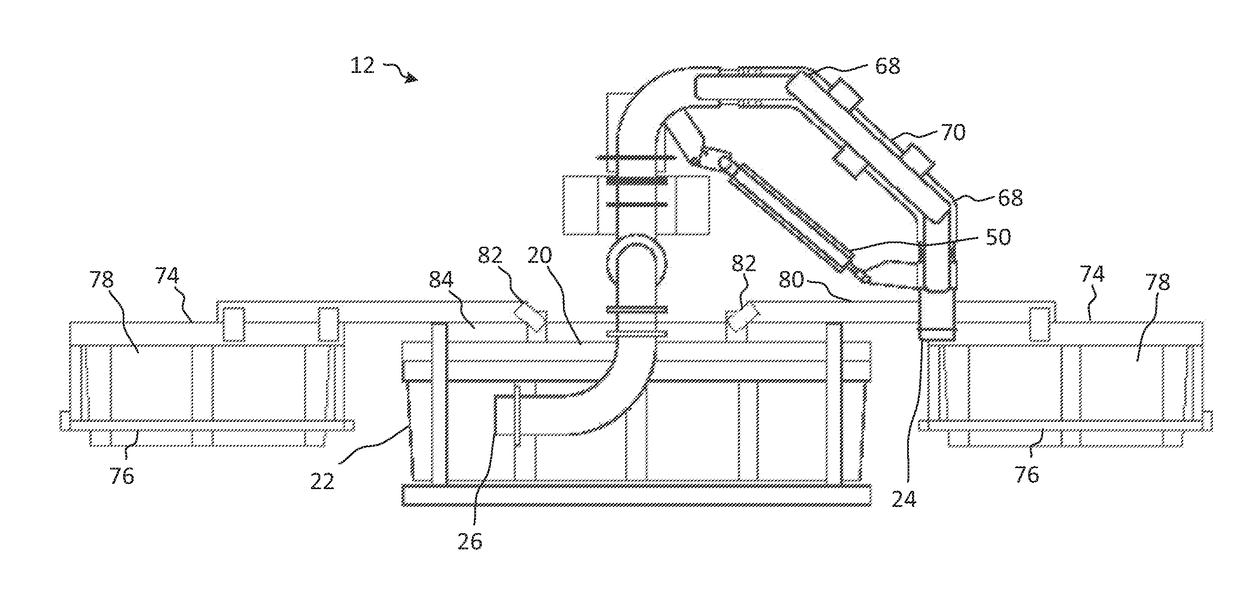
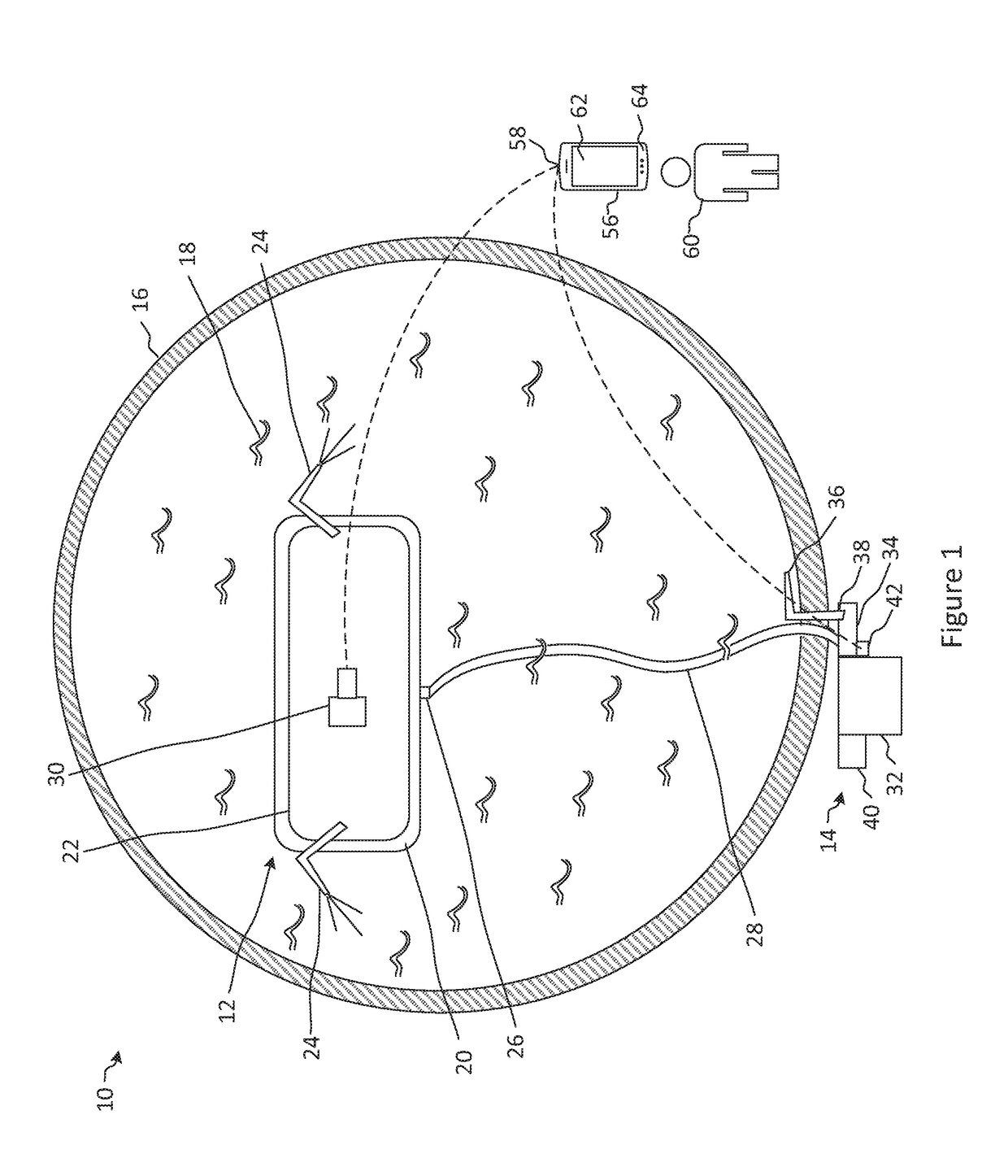
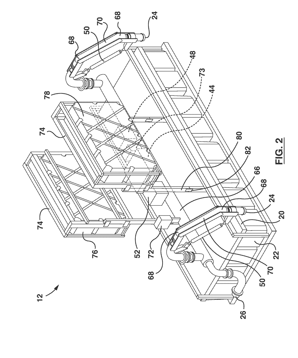
[0036]Referring to FIG. 1, illustrated therein is a manure agitation system 10, in accordance with an embodiment. The manure agitation system 10 includes a manure agitation vessel 12 and a remote or land based power source 14 for providing pumped fluid to the manure agitation vessel 12.

[0037]The manure agitation vessel 12 is sized and shaped to be placed in a manure reservoir or storage ins...


PUM


Abstract

A system for agitating manure includes a vessel shaped to be placed in a manure storage installation. The vessel includes a vessel frame having floatation for providing floatation to the vessel, at least one outlet nozzle attached to the vessel frame for agitating the manure, and a control system attached to the vessel frame for controlling the direction of the at least one outlet nozzle. The system includes a land based power source separated from the vessel having a fluid pump for pumping fluid from a land based input nozzle to supply fluid to the at least one outlet nozzle on the vessel. The system includes a fluid conduit connecting the land based power source to the at least one outlet nozzle and a remote control for user control of the control system of the vessel.

Description

CROSS REFERENCE TO RELATED APPLICATION[0001]This application claims the benefit of U.S. Provisional Patent Application No. 62 / 370,760, filed Aug. 4, 2016, which is hereby incorporated by reference.TECHNICAL FIELD[0002]The embodiments disclosed herein relate to apparatus for agitating manure stored in reservoirs and, more particularly, to vessels having manure agitating apparatus adapted for use in earthen storage reservoirs, such as manure holding ponds, lagoons, and settling basins.INTRODUCTION[0003]Manure from livestock is an excellent source of fertilizer containing nitrogen, phosphorous and other nutrients desirable for enrichment of soil. Manure is also an important source of organic matter which, when added to soil, helps to improve soil composition, aeration, water infiltration and moisture-retention capability. Livestock produce a large amount of manure. Manure is in constant supply and a means of storage and preservation is therefore required.[0004]For this reason, earthen ...

Claims


Application Information

Patent Timeline
IPC IPC(8): B01F5/02B01F15/02B01F15/00B01F13/00B01F25/60
CPCB01F5/0225B01F15/00305B01F15/0243B01F13/0049Y10S261/75B63B35/00B01F25/2124B01F25/50B01F33/503B01F35/2205C02F2201/008B01D1/0005B01F25/2121B01F25/20B01F35/7176
Inventor BEARINGER, LARRY
Owner 1863385 ONTARIO INC
Learn More