Multimode electromechanical variable speed transmission apparatus with smooth mode shifting and method of controlling the same

a multi-mode electromechanical variable and speed transmission technology, applied in mechanical devices, transportation and packaging, etc., can solve the problems of not being suitable for all electric drives, limiting the effective operating speed ratio range of the transmission, and reducing the efficiency of the transmission, so as to facilitate non-interruptive shifting, improve the efficiency of power transmission, and reduce the effect of power interruption

Inactive Publication Date: 2018-02-08
AI XIAOLIN +2
View PDF0 Cites 7 Cited by
  • Summary
  • Abstract
  • Description
  • Claims
  • Application Information

AI Technical Summary

Benefits of technology

[0009]One of the objectives of current invention is to provide novel multi-mode electro-mechanical variable speed transmissions that facilitate non power-interruptive shifting between operation modes using simple, compact and highly efficient positive engagement clutches. These transmissions can operate under at least two different power split modes, offering higher power transmission efficiency by avoidi

Problems solved by technology

Internal power circulation reduces the efficiency of the transmission and, to a large extent, constrains the effective operating speed ratio range of the transmission.
This makes THS not suitable for all electric drive in power demanding applications.
The major disadvantage of frictional clutch is high power loss due to frictional heat generation in the slippage pha

Method used


Image

  • Multimode electromechanical variable speed transmission apparatus with smooth mode shifting and method of controlling the same
  • Multimode electromechanical variable speed transmission apparatus with smooth mode shifting and method of controlling the same
  • Multimode electromechanical variable speed transmission apparatus with smooth mode shifting and method of controlling the same

Examples


embodiment 1

[0067]FIGS. 4 to 6 show a preferred embodiment, current invention. The embodiment is illustrated in the lever diagram format. The multi-mode electro-mechanical variable speed transmission is comprised of a gear system including a first planetary gear set (PG1) represented by a first lever and a second planetary gear set (PG2) represented by a second lever, an input shaft (Input), an output system (Output), at least one clutch (CL), a first stationary member (FM1), and a first and second electric machines (EM1, EM2) along with their associated drives and controllers (see FIG. 19).

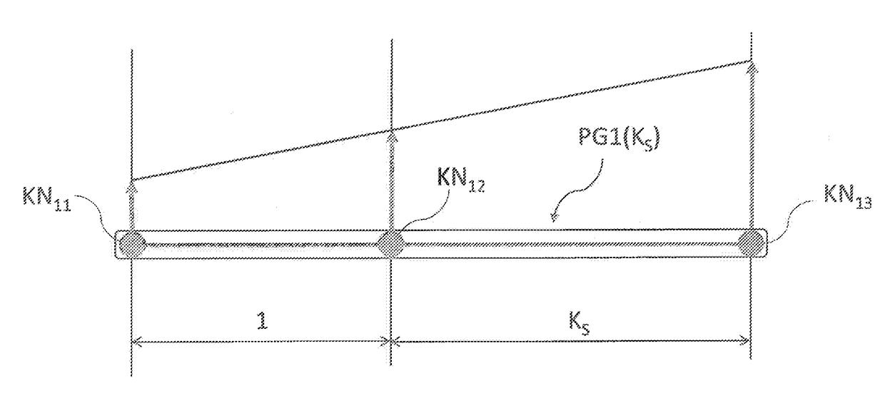
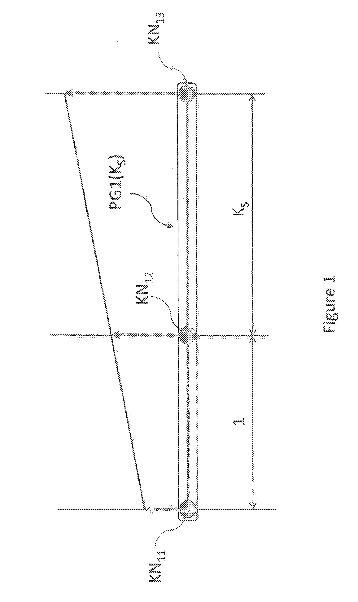
[0068]The first planetary gear set (PG1) is a three-branch planetary gear set, having a first co-axial rotatable component, a second co-axial rotatable component and a third co-axial rotatable component each being represented by a first knot (KN11), a second knot (KN12) and a third knot (KN13) of the first lever, respectively. The second planetary gear set (PG2) is a four-branch planetary gear set, having a ...

second embodiment

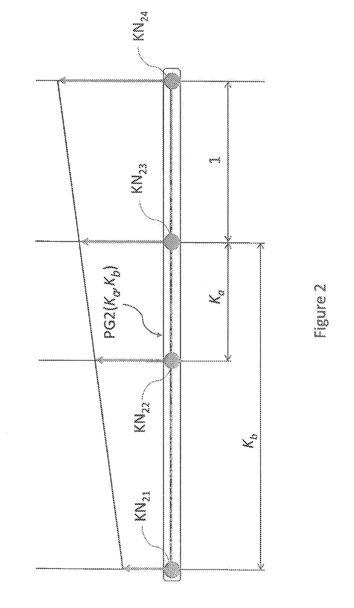
[0143]As shown in FIG. 15, the multi-mode electro-mechanical variable speed transmission is comprised of a planetary gear set (PG2) represented by a four-knot lever diagram having a first co-axial rotatable component (KN21), a second co-axial rotatable component (KN22), a third co-axial rotatable component (KN23) and a fourth co-axial rotatable component (KN24), a first pair of external meshing gears represented by a first two-knot lever (GP1), a second pair of external meshing gears represented by a second two-knot lever (GP2) and a third pair of external meshing gears represented by a third two-knot lever (GP3). The first two-knot lever (GP1) includes a first and second knots (KN31 and KN32) representing two rotatable external meshing gears. The second two-knot lever (GP2) includes a first and a second knots (KN41 and KN42) representing two rotatable meshing gears. The third two-knot lever (GP3) includes a first and second knots (KN51 and KN52) representing two rotatable meshing g...

embodiment 3

[0155]FIG. 17 shows another embodiment (embodiment 3) in a lever diagram format. Referring to FIG. 17, the multi-mode electro-mechanical variable speed transmission is comprised of a gear system including a first planetary gear set (PG1) represented by a first lever and a second planetary gear set (PG2) represented by a second lever, an input shaft (Input), an output system (Output), at least one torque transfer device (CL) including a neutral position, a first stationary member (FM1), and a first and a second electric machines (EM1, EM2) along with their associated drives and controllers. The first planetary gear set is a three-branch planetary gear, having a first co-axial rotatable component, a second co-axial rotatable component and a third co-axial rotatable component each being represented by a first knot (KN11), a second knot (KN12) and a third knot (KN13) of the first lever (PG1), respectively. The first lever is fully defined by its characteristic parameter KS1. The second ...


PUM


Abstract

A multi-mode electro-mechanical variable speed transmission capable of providing two power split operation modes and at least one fixed output-to-input speed ratio operation mode. The transmission includes an input shaft, an output system, at least one planetary gear set having at least a first, second and third co-axial rotatable components, two electric machines, and at least one torque transfer device. The first co-axial rotatable component couples to the first electric machine with a constant speed ratio; the second co-axial rotatable component couples to the output system with a constant speed ratio; and the third co-axial rotatable component couples to the input shaft with a constant speed ratio; the second electric machine selectively couples to two different co-axial rotatable components of the planetary gear set with two different speed ratios. The transmission is configured to unload the torque transfer device, adjust engine power, shift one of the electric machines to a freewheeling state, and actively synchronize the speed of the electric machines with the speed of one of the engagement positions of the torque transfer device.

Description

BACKGROUND OF THE INVENTION[0001]The invention is related to a multi-mode electro-mechanical variable speed transmission in a powertrain, and to a method of operating the transmission and the powertrain. More specifically, it is related to a multi-mode electro-mechanical variable speed transmission with load free clutch shifting between different modes of operation. It is applicable to a wide variety of vehicles and power equipment.[0002]To reduce fuel consumption and emission, hybrid vehicles combine an electric power plant with a conventional internal combustion engine. The internal combustion engine operates in a certain range of speed and power. Inside this range, there usually exists a smaller regime where the engine archives the best performance. On the other hand, however, driving conditions vary enormously, not only in wheel speed but also in driving torque at the drive wheels. A combination of a given speed and torque defines a power state. Selectively operating the interna...

Claims


Application Information

Patent Timeline
IPC IPC(8): B60K6/445B60K6/383F16H3/12F16H3/72F16H3/66B60K6/387B60K6/365
CPCB60K6/445B60K6/387B60K6/383B60K6/365F16H3/728F16H3/66F16H3/12F16H2200/2005F16H2200/2007F16H2200/2023F16H2200/2035F16H2200/2038F16H2200/2066F16H2200/2097Y02T10/62
Inventor AI, XIAOLINAI, XIAOZHIJIANG AI, ALAN
Owner AI XIAOLIN
Why Eureka
Try Eureka