Solid-state imaging element, imaging device, and electronic apparatus
a technology of solid-state imaging and imaging elements, applied in the direction of distance measurement, radiation control devices, instruments, etc., can solve the problems of difficult to obtain correspondence between the electric charge signals of the photodiode and the exit pupil region, the difficulty of distance measurement accuracy, etc., to achieve suppression of color mixing, high image height portion, and enhanced focusing accuracy and sensitivity
- Summary
- Abstract
- Description
- Claims
- Application Information
AI Technical Summary
Benefits of technology
Problems solved by technology
Method used
Image
Examples
first embodiment
[0066]Referring to FIG. 3, a configuration example of the back surface irradiation type solid-state imaging element to which the present technology has been applied will be described below. Here, the left part of FIG. 3 is a side sectional view of a general concept of an imaging device utilizing the solid-state imaging element, the central part of FIG. 3 depicts a configuration of a side section of an on-chip lens at an image height center in the solid-state imaging element to which the present technology has been applied, and the right part of FIG. 3 depicts a configuration of a side section of an on-chip lens at a high image height of the solid-state imaging element to which the present technology has been applied.
[0067]Specifically, as depicted in the left part of FIG. 3, the imaging device to which the present technology has been applied includes a main lens 51 and a solid-state imaging element 52.
[0068]The main lens 51 focuses light from a subject onto the solid-state imaging e...
second embodiment
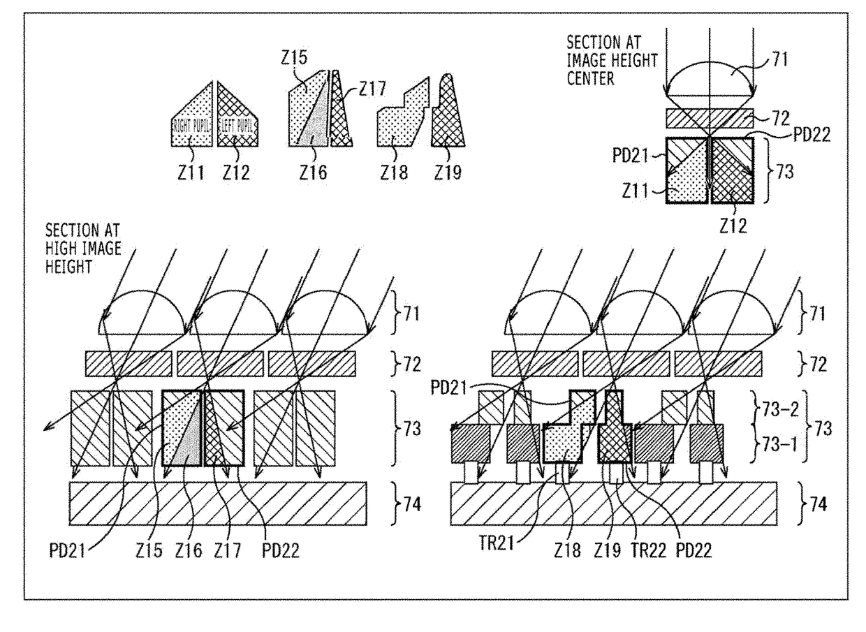
[0080]While an example wherein the photodiodes in the photodiode layer 73 which share the on-chip lens each include a single implant has been described hereinabove, the photodiodes may each include multiple stages of implants such as to have a shape close to a light distribution required, in accordance with the distance from an optical axis.
[0081]FIG. 5 depicts a configuration example of a back surface irradiation type solid-state imaging element wherein photodiodes each include multiple stages of implants such as to have a shape close to a light distribution required, in accordance with the distance from an optical axis. Note that the configurations having equivalent functions to those of the configurations in FIG. 3 are given the same names and denoted by the same reference signs as used above, and descriptions of them are appropriately omitted.
[0082]Note that in the following, the configuration of photodiodes PD21 and PD22 in pixels that share an on-chip lens in the center will b...
third embodiment
[0108]While an example wherein the photodiodes PD are formed by two stages of implants in forming the photodiodes PD by multiple stages of implants has been described hereinabove, the photodiodes PD may be formed by more stages of implants.
[0109]FIG. 10 depicts a configuration example of a solid-state imaging element wherein photodiodes PD21 and PD22 are formed by n stages of implants. Specifically, there is depicted that the photodiode layer 73 is formed from n stages of implants 73-1 to 73-n.
[0110]Where the photodiodes PD21 and PD22 are formed by further multiple stages of implants in this way, a shape close to a light distribution can be thereby obtained, so that focusing accuracy and sensitivity can be enhanced with higher accuracy, and color mixing can be suppressed.
[0111]It is to be noted, however, that an increase in the number of stages of implants for forming the photodiodes causes a rise in manufacturing cost, and, therefore, it is desirable to determine the number of sta...
PUM
 Abstract
Description
Claims
Application Information
 - R&D
- Intellectual Property
- Life Sciences
- Materials
- Tech Scout
- Unparalleled Data Quality
- Higher Quality Content
- 60% Fewer Hallucinations
Browse by: Latest US Patents, China's latest patents, Technical Efficacy Thesaurus, Application Domain, Technology Topic, Popular Technical Reports.
© 2025 PatSnap. All rights reserved.Legal|Privacy policy|Modern Slavery Act Transparency Statement|Sitemap|About US| Contact US: help@patsnap.com


