Exhaust gas treatment apparatus

a gas treatment apparatus and exhaust gas technology, applied in lighting and heating apparatus, combustion types, machines/engines, etc., can solve the problem of generating a large amount of nitrogen oxide (nox) additionally, and achieve the effect of suppressing the generation of co in the case of a low-temperature flame, small heat dissipation, and low cos

Active Publication Date: 2018-02-22
EBARA CORP
View PDF1 Cites 1 Cited by
  • Summary
  • Abstract
  • Description
  • Claims
  • Application Information

AI Technical Summary

Benefits of technology

[0032]According to the present invention, by blowing the fuel (fuel gas), the oxidizing gas (oxygen-containing gas), and the processing gas (exhaust gas) into the combustion chamber, respectively, in a tangential direction to the inner circumferential surface of the cylindrical combustion chamber, the fuel and the processing gas are combusted by the oxidizing gas to form a cylindrical mixed flame. Specifically, in the combustion chamber, the cylindrical mixed flame of a mixture of the three kinds of gases is formed in the same combustion field, and the processing gas is combusted. Therefore, the following effects can be obtained.
[0033](1) By introducing the three kinds of gases, respectively, in a tangential direction to the inner circumferential surface of the combustion chamber, a distribution in which a gas having a high temperature and a light weight after combustion is positioned at an inner part of the cylindrical mixed flame, and an unburned gas having a low temperature and a heavy weight is positioned at an outer part of the cylindrical mixed flame is formed by a swirling centrifugal force. Because the cylindrical mixed flame is in a thermally self-insulated state due to structure of the flame, heat dissipation is small and high-efficiency combustion can be performed. Therefore, generation of CO generated in the case of a low-temperature flame can be suppressed, and heat damage of the combustion chamber can be prevented.
[0034](2) By mixing and combusting the three kinds of gases, a flame having no local high-temperature part is formed, and hence generation of thermal NOx can be suppressed and melting or adhesion of the by-product can be prevented.
[0035](3) By mixing the three kinds of gases, the fuel and oxygen are diluted with N2 gas as a main component of the inflow gas, and thus a ratio of unburned gas at the outer part of the cylindrical mixed flame is increased to cause a diameter of the flame to be small. Specifically, self-heat insulating properties of the flame can be promoted.
[0036](4) By mixing and combusting the three kinds of gases, the flame whose self-heat insulating properties are improved is formed. Therefore, even if water for forming wet wall is flowed outside the flame, the water and the high-temperature flame are not brought into direct contact with each other. Because the temperature rise of water can be suppressed, the mixed combustion and heat insulation flame can be formed inside the wet wall without lowering the combustion efficiency. Therefore, the following effects can be obtained.
[0037]A. The ignition position of the cylindrical mixed flame is located immediately below the port for an inflow gas, and oxidation reaction of the inflow gas is initiated from the position of the water for forming wet wall. Because the powdery product such as SiO2 generated by oxidation reaction is collected by water for forming wet wall due to a swirling centrifugal force, the powdery product is not deposited in the combustion chamber. The produced powdery product such as SiO2 is collected by the water for forming wet wall due to the swirling centrifugal force immediately after its production, and hence the efficiency for removing the powdery product as an abatement device can be improved. Specifically, the scrubber performance can be improved.

Problems solved by technology

However, this method is problematic in that nitrogen contained in the exhaust gas is decomposed by the high-temperature flame resulting from the attributes of pure-oxygen combustion, thereby generating a large amount of nitrogen oxide (NOx) additionally.
Further, this method has a problem of generating CO because the flame has a low temperature.

Method used


Image

  • Exhaust gas treatment apparatus
  • Exhaust gas treatment apparatus
  • Exhaust gas treatment apparatus

Examples


Embodiment Construction

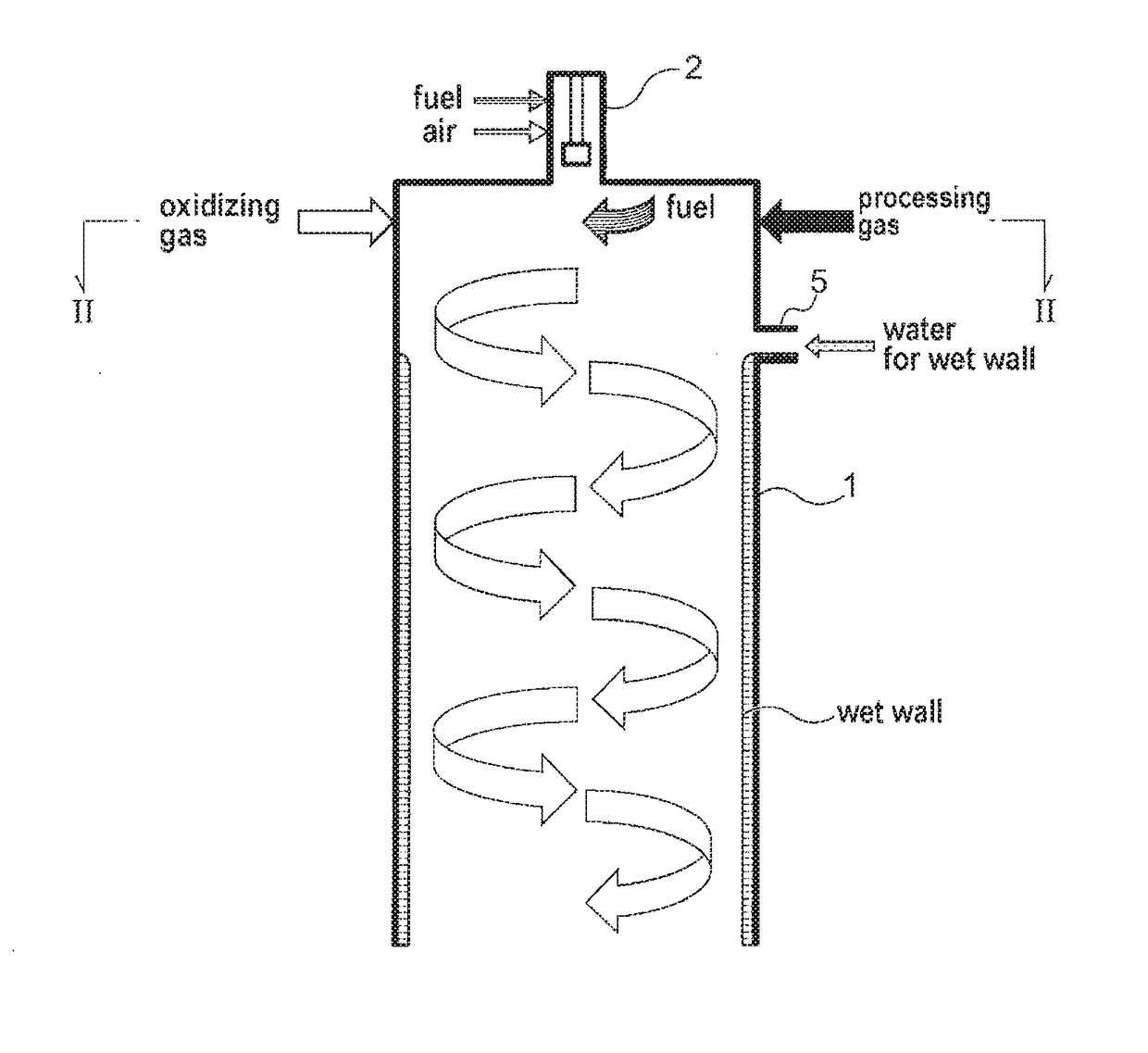
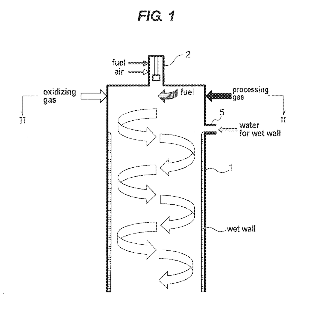
[0047]An exhaust gas treatment apparatus according to embodiments of the present invention will be described with reference to FIGS. 1 through 6. In FIGS. 1 through 6, identical or corresponding parts are denoted by identical or corresponding reference numerals throughout views, and will not be described in duplication.

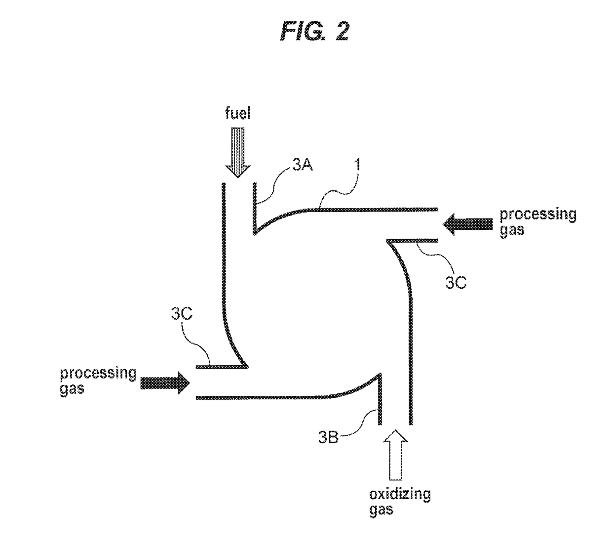
[0048]FIG. 1 is a schematic cross-sectional view showing a structural example of a combustion chamber of the exhaust gas treatment apparatus according to the present invention. A combustion chamber 1 is configured to be a cylindrical container-shaped combustion chamber having one end (an upper end in the illustrated example) which is closed and the other end (a lower end in the illustrated example) which is open. The cylindrical container-shaped combustion chamber 1 is configured so that a fuel (fuel gas), an oxidizing gas (oxygen-containing gas) and a processing gas (exhaust gas) are blown into the combustion chamber 1 in the vicinity of the closed end portion. A pil...


PUM

PropertyMeasurementUnit
diameteraaaaaaaaaa
sizeaaaaaaaaaa
swirling forceaaaaaaaaaa

Abstract

A hybrid stepping motor has a connector housing formed integrally with an insulator having an upper insulator and a lower insulator. The hybrid stepping motor includes a stator core and output terminals concentrically disposed outside the stator core. A wiring pattern serving as the output terminals has connector pins and land portions disposed eccentrically with respect to one another. The land portions are formed on an outer edge side of the wiring pattern. A surface, which is an uppermost surface of the wiring pattern, is located below a lowermost surface, in which jumper wires and lead wires pass, of the lower insulator. The lead wires are pulled out from a lower side, and are pulled out to guiding grooves.

Description

TECHNICAL FIELD[0001]The present invention relates to an exhaust gas treatment apparatus for treating an exhaust gas, discharged from a manufacturing apparatus or the like for manufacturing semiconductor devices, liquid crystals, LEDs or the like, by combustion treatment to make the exhaust gas harmless.BACKGROUND ART[0002]Gases including a harmful and combustible gas, such as silane gas (SiH4) or halogen-based gas (NF3, ClF3, SF6, CHF3, C2F6, CF4), are discharged from a semiconductor manufacturing apparatus. Such an exhaust gas (processing gas) cannot be emitted into the atmosphere as it is. Therefore, the exhaust gas is generally introduced into an abatement apparatus where the exhaust gas is made harmless by oxidation through combustion. As this treatment method, a combustion-type exhaust gas treatment apparatus in which a fuel gas is used to form a flame in a furnace and to perform exhaust gas treatment therein is widely used.[0003]In a combustion-type exhaust gas treatment appa...

Claims


Application Information

Patent Timeline
Patent Type & Authority Applications(United States)
IPC IPC(8): F23G7/06F01N3/24F23C3/00F23M5/08F23L1/00
CPCF23G7/065F01N3/24F23C3/00F23M5/08F23L1/00B01D2257/20B01D2251/102B01D2258/0216F23G7/06F23L7/002F23D14/24F23G5/32F23G2203/30F23G2204/103F23G2209/142F23L2900/07008F23G2209/14
Inventor MIYAZAKI, KAZUTOMOKOMAI, TETSUOSHINOHARA, TOYOJIKASHIWAGI, SEIJI
Owner EBARA CORP
Why Eureka
Try Eureka