
System and method for electrochemical energy conversion and storage

a technology of energy conversion and electrochemical energy, applied in the field of energy storage systems, can solve the problems of limited implementation of such a “hydrogen economy, the design of a catalytic fuel-dehydrogenation reactor system that delivers hydrogen on demand from any lohc is itself a major engineering challenge and very costly

Inactive Publication Date: 2018-02-22
COLORADO SCHOOL OF MINES +1
View PDF4 Cites 5 Cited by
  • Summary
  • Abstract
  • Description
  • Claims
  • Application Information

AI Technical Summary

Benefits of technology

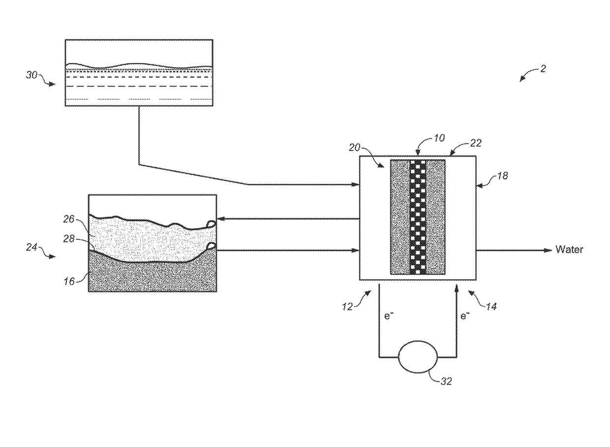
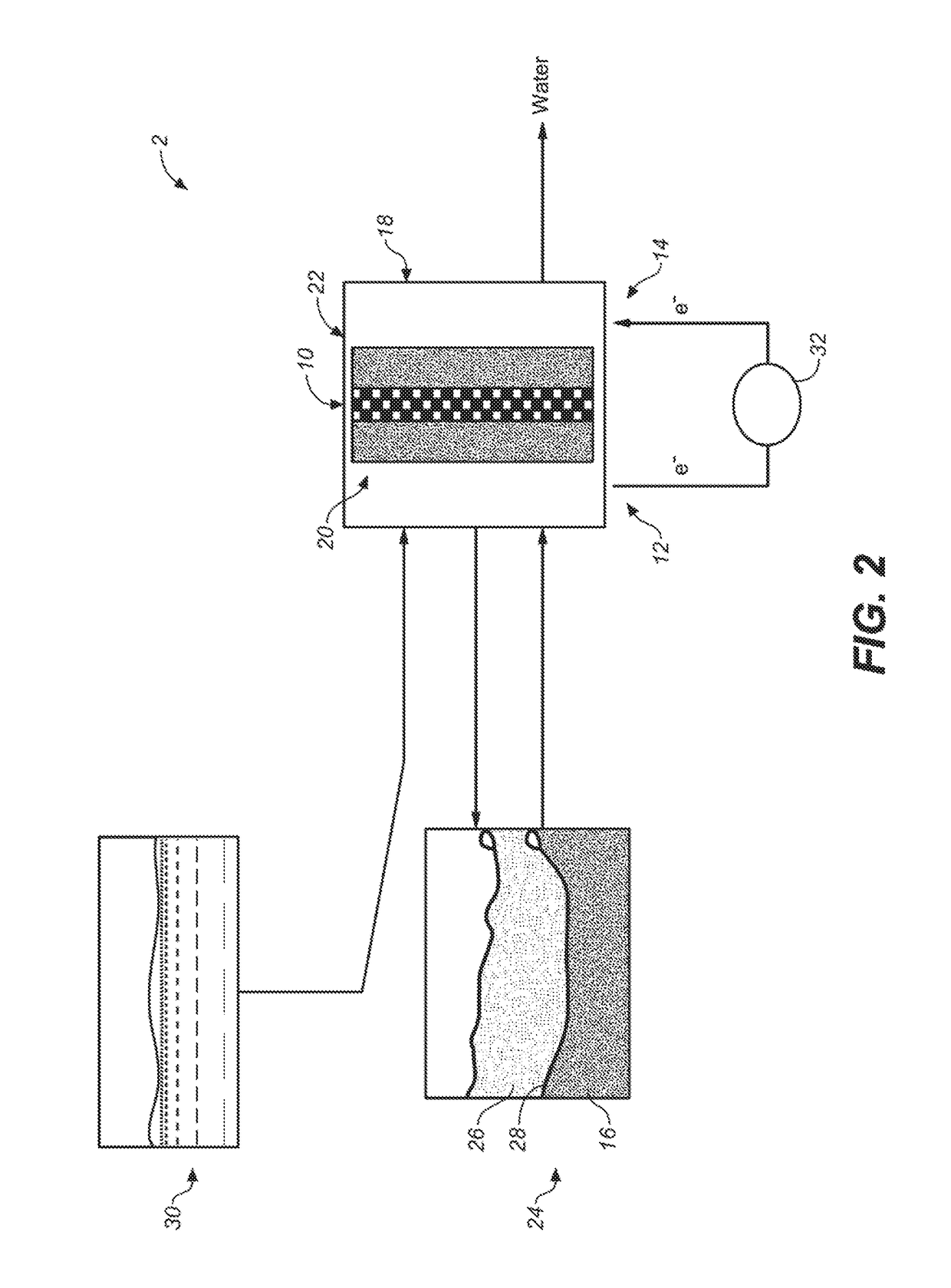
The invention is about an electrochemical energy conversion system that uses a hydrogen-regenerable or electrochemically regenerable liquid fuel and an oxidant to generate electricity. The system includes an electrochemical energy conversion device, such as a fuel cell, and a liquid fuel that is a mixture of different compounds. The liquid fuel is in fluid communication with the device and can be regenerated by a catalytic hydrogenation process. The system can also include a catalyst to assist in the oxidation of the fuel. The invention provides a direct fuel cell apparatus that can convert chemical energy into electrical energy using a hydrogen-regenerable liquid fuel and a membrane electrode assembly. The fuel can optionally contain water. The system can operate at a temperature between about 80°C to about 400°C. The invention also provides a method for regenerating the spent fuel by a catalytic hydrogenation process.

Problems solved by technology

The capital cost of establishing a hydrogen-transport infrastructure and the limitations in current vehicular hydrogen storage technologies have thus far resulted in only a very limited implementation of such a “Hydrogen Economy.”
This required energy input amounts to a loss of almost one-third of the lower heating value (LHV) of hydrogen in the absence of any heat integration.
Particularly for vehicular systems where size and weight are at a premium, the design of a catalytic fuel-dehydrogenation reactor system that delivers hydrogen on demand from any LOHC is itself a major engineering challenge and very costly.
While a pathway of directly using an H2-loaded LOHC carrier in a fuel cell has clearly evident advantages, as in obviating the need for a dehydrogenation reactor, it presents very significant challenges in fuel cell design.
Notably, the presence of the at least two oxygen heteroatoms in the carrier molecule limits the gravimetric hydrogen capacity.
But most importantly, there is no disclosure of experimental performance data (such as a measured OCV, and voltage and power density under load) for a fuel cell test device functioning with a claimed liquid organic hydrogen carrier.
The spent fuel is regenerated either electrically or ‘in sit’, the latter using relatively costly and non-easily regenerable chemical reducing agents as exemplified by lithium aluminum hydride and other highly reactive organometallic reductants.
Significantly, there is no teaching of the potential use of hydrogen (H2) for effecting such a regeneration of the fuel.

Method used


Image

  • System and method for electrochemical energy conversion and storage
  • System and method for electrochemical energy conversion and storage
  • System and method for electrochemical energy conversion and storage

Examples


examples 1-4 (

Computationally-Based)

Example 1

[0088]Electrochemical oxidative dehydrogenation of a mixture of perhydrogenated benzyltoluene isomers to a mixture of benzyltoluene isomers (for the estimation of ΔS, computationally modelled as 3-benzyltoluene).

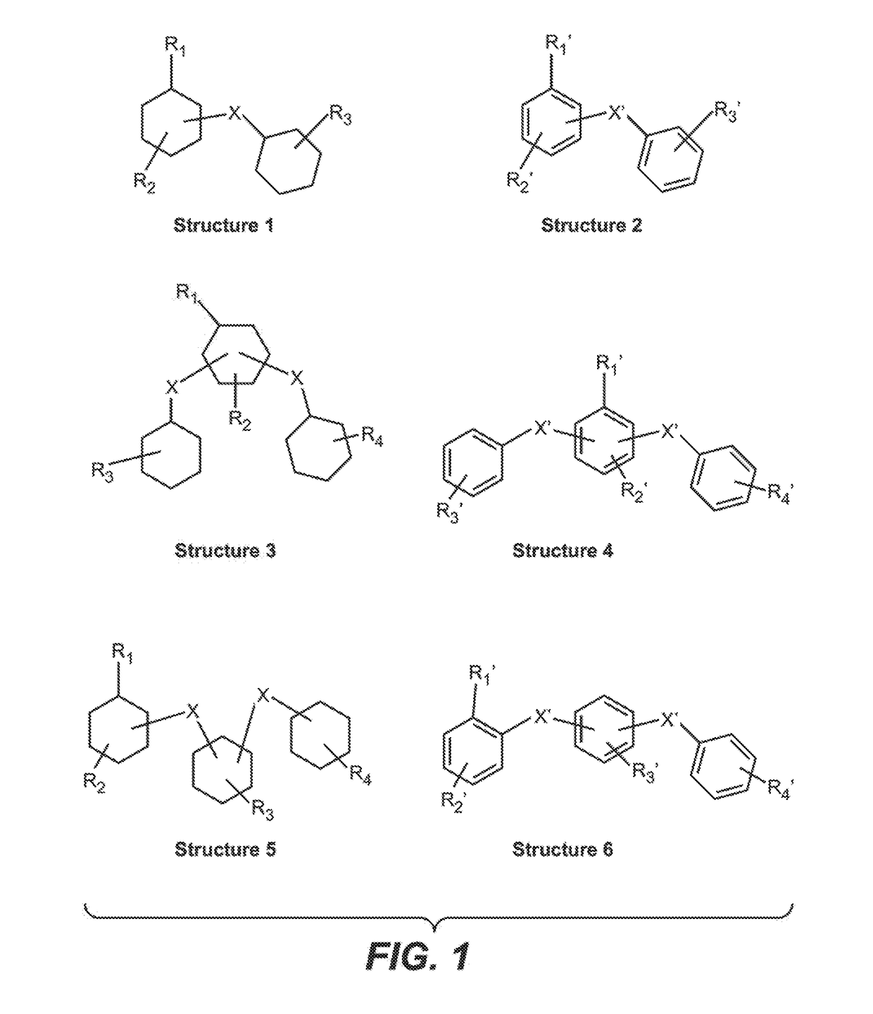
[0089]Referring to compositions and structures in FIG. 1:

[0090]Composition of Structure 1 with R1═CH3 as the only ring substituent and X═—CH2—, +3O2→Composition of Structure 2 with R1′═CH3 as the only ring substituent and X′═—CH2—, +6H2O: ΔG0=−1208 kJ / mole,*. Open circuit voltage (OCV)=1.259 V (n=12) Energy Density=6.215 kJ / gram or 1726 Wh / kg for the perhydrogenated benzyltoluene isomers / mixture of benzyltoluene isomers molecule pair.

*Estimated from Δ10 (gas) experimental data of perhydrobenzyltoluene, labeled as 12H MLH in Mueller et al., Eng. Chem. Res. 2045, 54, 79, and an entropy, ΔS (gas) taken from the SSPD data base, calculated at the EFD2 / 6-31G* level, from the SPARTAN™ 2016 Quantum Chem. Package (Wavefunction Inc.). Using the Δf0 (liqu...

example 2

[0091]A mixture of the same perhydrogenated benzyltoluene isomers as in Example 1 is converted to a mixture of benzyltoluene isomers and, in addition, the methylene group is selectively oxidized to a carbonyl group:

Structure 1 with R1=methyl (CH3) and X=methylene (—CH2—), +4O2→Structure 2 where now X′

is a bridging carbonyl, C(O)+7H2O; ΔG0=−1564 kJ / mole; OCV=1.013 V (n=16)

Energy density=8.047 kJ / gram or 2235 Wh / kg, for the perhydrogenated benzyltoluene isomers / mixture of benzoyltoluene isomers molecule pair.

The oxidation of the bridging methylene to a bridging carbonyl results in a 29% increase in energy density, or maximum energy storage capacity of the fuel.

example 3

[0092]As for Example 2, with in addition, a selective electrochemical oxidation of the methyl group to an aryl carboxylic acid group (—COOH):

Structure 1 with R1=methyl (CH3), X═—CH2—+5.5O2→Structure 2 where X′═C(O) and R1′═COOH; ΔG0=−2122 kJ / mole, OCV=1.0 V (n=22) Energy density 10.92 kJ / gram or 3030 Wh / kg

[0093]The oxidation of the methyl group to a carboxylic acid group provides an additional 35% increase in energy density. The two oxidation steps result in a total 75% increase in the energy storage capacity of the original fuel. A selective oxidation of added functional groups (R2 to R4) may be expected to lead to further enhancements in electrochemical energy storage capacity of the fuel.


PUM


Abstract

An electrochemical energy conversion and storage system includes an electrochemical energy conversion device, such as a fuel cell that is in fluid communication with a hydrogen or electrically regenerable organic liquid fuel and an oxidant, for receiving, catalyzing and electrochemically oxidizing at least a portion of the fuel to generate electricity, a thus partially oxidized liquid fuel, and water. The liquid fuel includes six-membered ring cyclic hydrocarbons with functional group substituents, wherein the ring hydrogens may undergo an electrochemical oxidative dehydrogenation to the corresponding aromatic molecules. Comprising ring-substituent functional groups may also be electrochemically oxidized now with a potential incorporation of oxygen thus providing an additional capacity for energy storage. The partially oxidized spent liquid fuel may be electrically regenerated in with now an input of electricity and water to the device, generating oxygen as a by-product. Alternatively, the recovered spent fuel may be conveyed to a facility where it is reconstituted by catalytic hydrogenation or electrochemical hydrogenation processes.

Description

CROSS-REFERENCE TO RELATED APPLICATION[0001]This application is a continuation-in-part of U.S. Provisional Patent Application Ser. No. 62 / 376,233, filed Aug. 17, 2016, the disclosure of which is hereby incorporated by reference in its entirety to provide continuity of disclosure to the extent such a disclosure is not inconsistent with the disclosure herein.BACKGROUND OF THE INVENTION[0002]The invention relates generally to a system for energy storage and specifically to materials, methods and apparatus for electrochemical energy conversion and storage using a hydrogen or electrically regenerable liquid fuel.[0003]Many electrochemical energy conversion and storage devices such as secondary batteries, electrochemical capacitors and fuel cells are known. The battery and capacitor devices directly store an input of electrical energy. It is known that fuel cells are inherently energy conversion devices which by electrochemical processes can transform the inherent energy of a potentially ...

Claims


Application Information

Patent Timeline
IPC IPC(8): H01M8/1009H01M8/1004H01M4/92H01M4/90
CPCH01M8/1009H01M4/9083H01M4/926H01M8/1004H01M8/103H01M8/188H01M2008/1095H01M2250/20C01B3/22C01B2203/0277C01B2203/066C01B3/0015Y02E60/32Y02T90/40Y02E60/50
Inventor PEZ, GUIDOHERRING, ANDREW MICHAEL
Owner COLORADO SCHOOL OF MINES
Learn More