
Irradiation device for introducing infrared radiation into a vacuum processing chamber using an infrared emitter capped on one end

a vacuum processing chamber and infrared radiation technology, which is applied in the direction of leading-in conductors, electric heating, electrical apparatus, etc., can solve the problems of low operating power, high specific electrical resistance of tantalum, and high heat build-up, and achieve low thermal conductivity and low operating power. , the effect of excluding the risk of short circuit caused by twisting or sagging of the heating conductor

Inactive Publication Date: 2018-02-22
HERAEUS NOBLELIGHT GMBH
View PDF0 Cites 4 Cited by
  • Summary
  • Abstract
  • Description
  • Claims
  • Application Information

AI Technical Summary

Benefits of technology

The invention provides an irradiation device that can safely and reliably operate in vacuum processing chambers. The device is designed to avoid the limitations of prior art and allows for long IR emitters to be used without the need for additional components or cooling. The device is simple to use and ensures high heating output.

Problems solved by technology

The operation of infrared emitters in a vacuum or in vacuum processes with reactive atmospheres, in which a significant amount of heat is to be applied to a substrate to be processed in a short amount of time, represents a special challenge to the components and materials in use.
This results in the problem of finding suitable, electrically conductive materials for the heating filaments and their connections, wherein these materials simultaneously have a melting point of greater than 2000° C. and a similar coefficient of thermal expansion throughout the temperature range from room temperature up to the processing temperature of quartz glass.
In such emitters, heat builds up even in the area of the tube ends and this affects, in particular, the seals.
The problems mentioned above can indeed be counteracted by an accordingly low operating power of the emitter, which, however, would be counterproductive in the sense of the heating output required for the respective treatment process in the processing chamber.
Such flanges, however, must be held so that they can move in the direction of the emitter axis against the processing chamber wall, in order not to convert slight thermal expansion into tensile stress that is destructive to the emitter tube: because the thermal expansion of the quartz glass is lower by approximately one order of magnitude than that of the metallic chamber wall, even slight variations of the temperature of the chamber wall or the casing tube made of quartz glass could lead to problems with respect to a compression-resistant and thermally stable seal or current feedthrough.
The use of vacuum feedthroughs for emitter tubes is therefore also associated with risks.
The production of such an exactly positioned, opaque tube section is complicated.
A disadvantage in this arrangement is that an additional component in the form of the pushed-on tube section is required.
In the sense of a space-saving arrangement of the IR emitter and the lowest possible risk for vacuum leakage, however, relatively large openings in the chamber wall are counterproductive.
The device for corresponding cooling, however, is complicated, susceptible to disruptions, and contradicts the requirement of the most effective possible heating output with respect to the material to be processed in the vacuum processing chamber.

Method used


Image

  • Irradiation device for introducing infrared radiation into a vacuum processing chamber using an infrared emitter capped on one end
  • Irradiation device for introducing infrared radiation into a vacuum processing chamber using an infrared emitter capped on one end
  • Irradiation device for introducing infrared radiation into a vacuum processing chamber using an infrared emitter capped on one end

Examples


Embodiment Construction

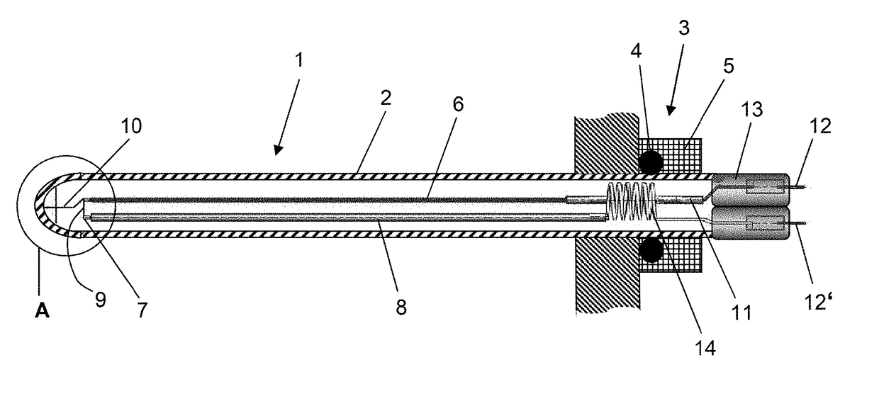
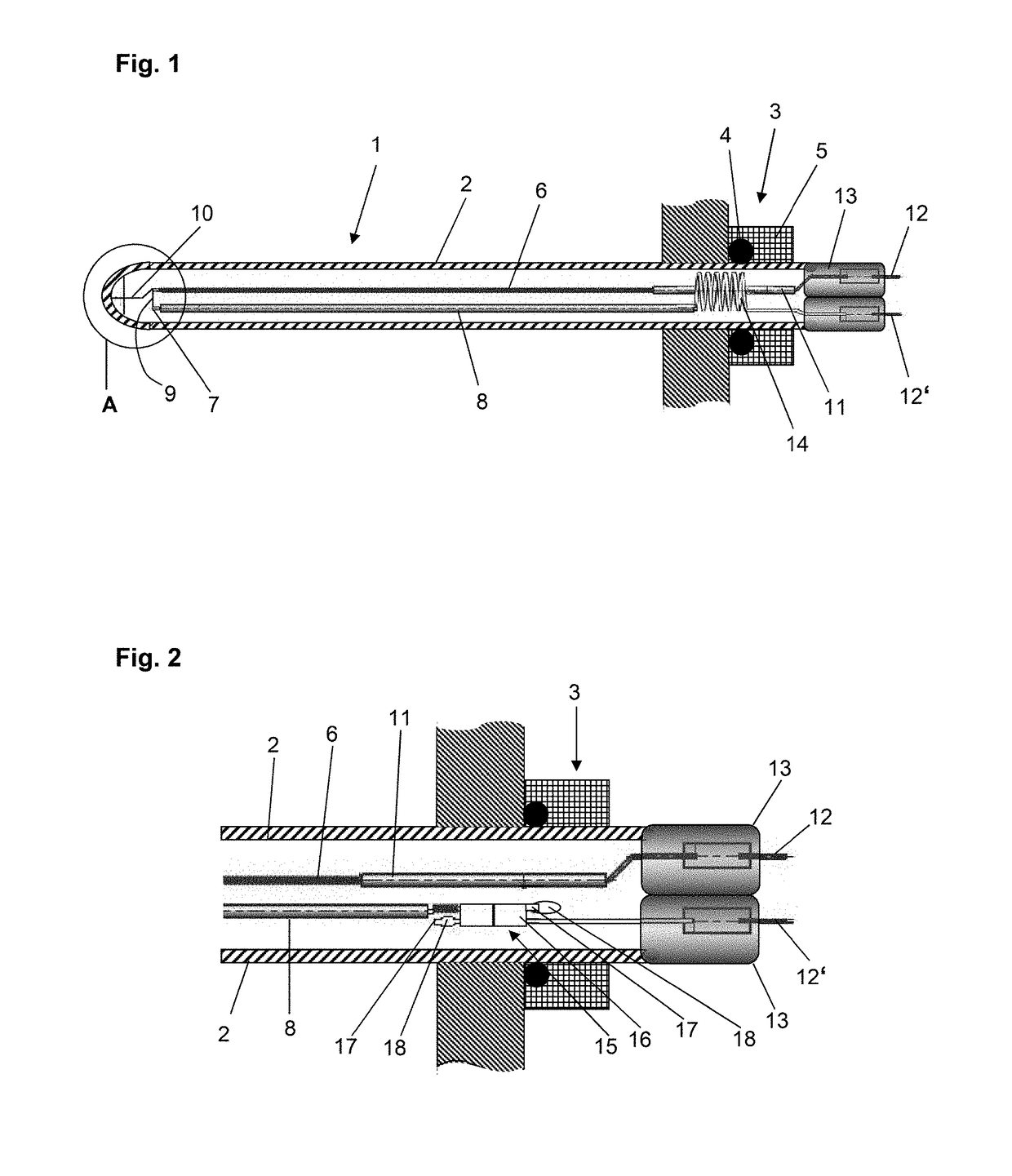
[0044]FIG. 1 shows schematically an infrared emitter 1 having an axial-symmetric emitter casing tube 2 made of quartz glass having round cross section (outer diameter 19 mm). The infrared emitter 1 is held by a vacuum feedthrough 3, which comprises a sealing ring 4 and a type of gland 5, in the opening of a vacuum processing chamber and projects with its closed end into the vacuum processing chamber. The IR emitter 1 is designed for an operating temperature above 800° C.

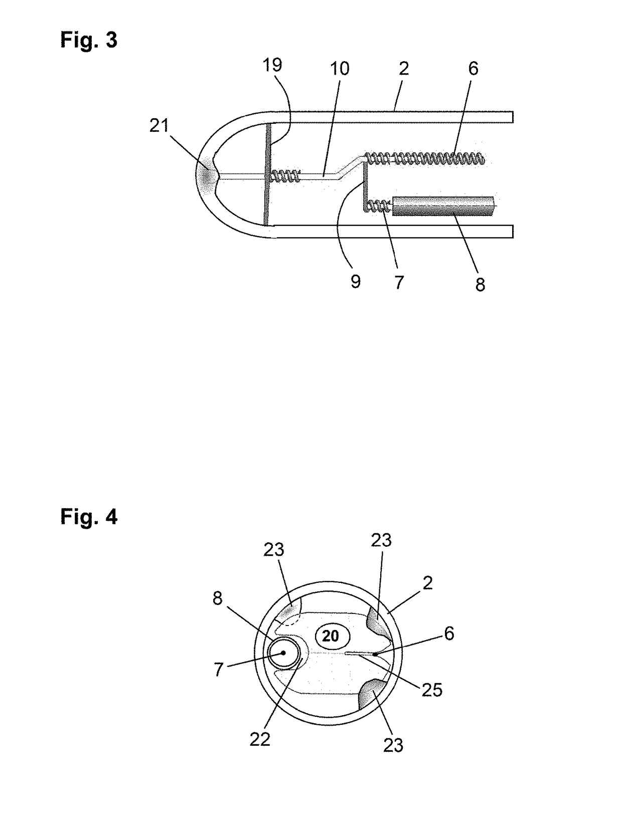
[0045]In the emitter casing tube 2 there is a coil-shaped heating conductor 6 (heating filament) made of tungsten having a (heated) length of 140 cm and a return conductor 7 (current return). The return conductor 7 is guided parallel to the heated area of the heating conductor 6 in a quartz glass tube 8. In the area of the closed end of the emitter casing tube 2, the heating conductor 6 and return conductor 7 are connected to each other by a short connecting piece 9. Furthermore, a support element 10 is located there...


PUM


Abstract

An irradiation device for introducing infrared radiation into a vacuum processing chamber has an infrared emitter capped on one end and including an emitter casing tube in the form of a round glass tube, of which a closed end projects into the vacuum processing chamber. A vacuum feedthrough holds the emitter casing tube and leads it in a gas-tight manner through an opening of the vacuum processing chamber. A heating filament and a current return are arranged in the emitter casing tube, wherein the heating conductor has, in the section of the emitter casing tube surrounded by the vacuum feedthrough, a connection element that is led out from the emitter casing tube. The connection element of the heating conductor is guided through a tube section and the return conductor has, in the section of the emitter casing tube surrounded by the vacuum feedthrough, a means for compensating for thermal expansion.

Description

CROSS-REFERENCE TO RELATED APPLICATIONS[0001]This application is a Section 371 of International Application No. PCT / EP2015 / 081155, filed Dec. 23, 2015, which was published in the German language on Sep. 1, 2016, under International Publication No. WO 2016 / 134808 A1 and the disclosure of which is incorporated herein by reference.BACKGROUND OF THE INVENTION[0002]The present invention relates to an irradiation device for introducing infrared radiation into a vacuum processing chamber, using an infrared emitter capped on one end, which comprises an emitter casing tube in the form of a round tube made of glass, of which a closed end projects into the vacuum processing chamber, and having a vacuum feedthrough for holding the emitter casing tube and guiding it in a gas-tight way through an opening of the vacuum processing chamber, wherein a heating conductor constructed as a heating filament and a return conductor constructed as a current return are arranged in the emitter casing tube, whe...

Claims


Application Information

Patent Timeline
IPC IPC(8): H05B3/00H01K7/00H01K1/20H01K1/40
CPCH05B3/0038H01K7/00H01K1/20H01K1/40H01K1/18H05B3/44
Inventor GROB, SIEGFRIEDKLINECKY, MARTINPIELA, THOMASLINOW, SVENMEYER, THOMAS
Owner HERAEUS NOBLELIGHT GMBH
Learn More