Steering control device

a control device and steering technology, applied in the direction of electric steering, power steering steering, vehicle components, etc., can solve the problems of end abutment, difficult control of current, and inability to obtain an accurate value of current immediately before the end abutment, so as to reduce the magnitude of voltage, suppress the occurrence of situations, and increase the gain of integral elements

Inactive Publication Date: 2018-03-01
JTEKT CORP +1
View PDF1 Cites 4 Cited by
  • Summary
  • Abstract
  • Description
  • Claims
  • Application Information

AI Technical Summary

Benefits of technology

[0020]In the above configuration, before the turning angle reaches the limit angle, the output value of the integral element tends to be an appropriate value for the magnitude of the induced voltage before the turning angle reaches the limit angle such that the current flowing through the motor is controlled to the current command value. In addition, based on the fact that the magnitude of the detected value of the current exceeds the magnitude of the current command value, the feedback processing portion executes control to decrease the magnitude of the voltage that is applied to the motor. Thus, the control of decreasing the m

Problems solved by technology

However, when a time constant of the low pass filter does not correspond to the rotational speed of the motor immediately before the end abutment, it is not possible to obtain an accurate value of the current immediately before the end abutment.
Thus, it is difficult to control the current at the time at which the end abutment occurs, to the

Method used


Image

  • Steering control device
  • Steering control device
  • Steering control device

Examples


first embodiment

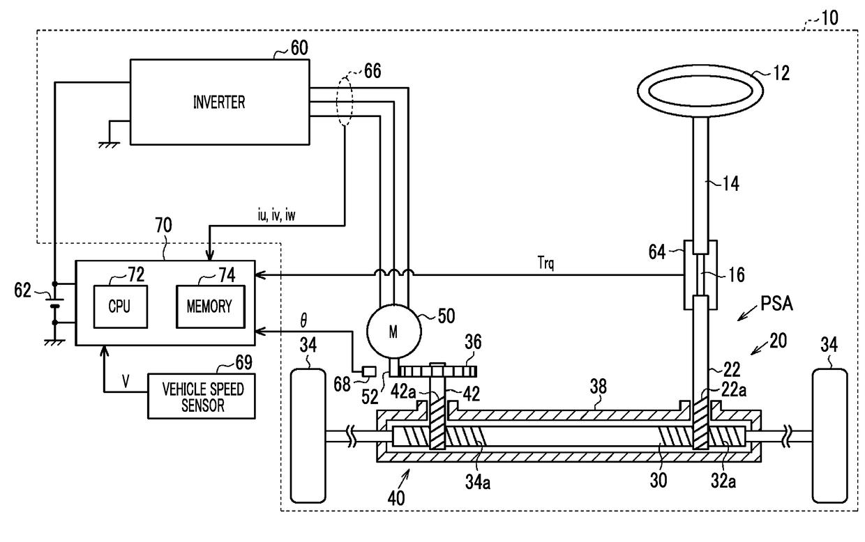
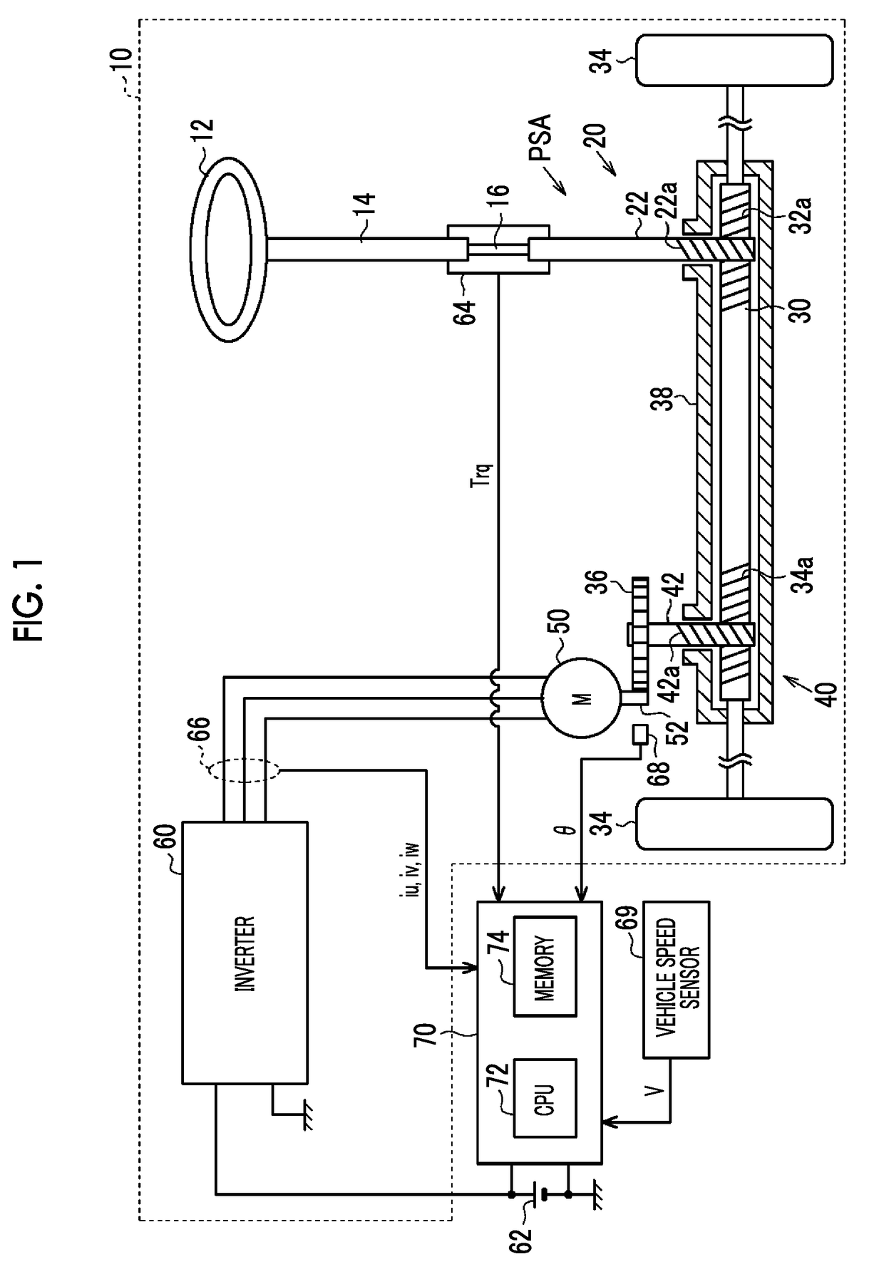
[0031]A steering control device according to the disclosure will be described with reference to the drawings. As shown in FIG. 1, in a steering system 10 according to the embodiment, a steering wheel 12 can be coupled to a pinion shaft 22 of a turning actuator PSA via a steering shaft 14. The turning actuator PSA includes a first rack and pinion mechanism 20, a second rack and pinion mechanism 40, a surface permanent magnet synchronous motor (SPM) (hereinafter, may be referred to as “motor 50”), and an inverter 60.

[0032]The first rack and pinion mechanism 20 includes a rack shaft 30 and the pinion shaft 22 that are arranged at a specified crossing angle, and first rack teeth 32a formed on the rack shaft 30 mesh with pinion teeth 22a formed on the pinion shaft 22. Note that steered wheels 34 are respectively coupled to both ends of the rack shaft 30 via tie rods.

[0033]The second rack and pinion mechanism 40 includes the rack shaft 30 and a pinion shaft 42 that are arranged at a speci...

second embodiment

[0125]With regard to the end-time limit processing portion, for example, in the above second embodiment, the conditions for ending the processing of limiting the current command value iq* with the use of the end-time current command value iqth may be changed as follows. More specifically, instead of executing the processing in step S72 in FIG. 7, only a condition that the current command value iq1* is equal to or smaller than the end-time current command value iqth may be used. Instead of executing the processing in step S78, only a condition that the current command value iq1* is equal to or larger than the end-time current command value iqth may be used.

[0126]The limit angle as the upper limit value of the absolute value of the turning angle of the steered wheels 34 is not limited to the turning angle at the time when the rack shaft 30 comes into contact with the rack housing 38, the limit angle being determined by a structure of the steering system 10. For example, in the case wh...


PUM


Abstract

A steering control device includes a feedback processing portion configured to control a current flowing through a motor to a current command value; an end determination processing portion configured to determine whether a turning angle of steered wheels has reached a limit angle; and an end-time limit processing portion configured to limit a magnitude of the current command value to a magnitude of a limited current value or smaller, when the end determination processing portion determines that the turning angle has reached the limit angle. The limited current value is a value obtained by performing correction to decrease a magnitude of a detected value of the current flowing through the motor at a time when the end determination processing portion determines that the turning angle has reached the limit angle, based on a degree of a decrease in a magnitude of a rotational speed of the motor.

Description

INCORPORATION BY REFERENCE[0001]The disclosure of Japanese Patent Application No. 2016-165884 filed on Aug. 26, 2016 including the specification, drawings and abstract is incorporated herein by reference in its entirety.BACKGROUND1. Technical Field[0002]The disclosure relates to a steering control device configured to control a steering system, the steering system including a turning actuator that turns steered wheels of a vehicle, and the steering system assisting turning of the steered wheels in accordance with steering of a steering wheel.2. Description of Related Art[0003]For example, in Japanese Patent Application Publication No. 2009-143312 (JP 2009-143312 A), a steering control device is described. The steering control device executes control that reduces an impact that is generated at a time when a steering angle of a steering wheel reaches a specified amount, which leads to so-called end abutment, and thus, a turning angle of steered wheels reaches a limit angle. The contro...

Claims


Application Information

Patent Timeline
IPC IPC(8): B62D5/04B62D3/12
CPCB62D5/0469B62D3/12B62D5/0463B62D5/046
Inventor TOKO, TAKAHIROTAMAKI, HIROMASAHASEGAWA, JUNFUJITA, SHOHEIYANAI, KOHEISUZUKI, TATSUYA
Owner JTEKT CORP
Why Eureka
Try Eureka