Solid Particle Erosion Indicator Module For A Valve And Actuator Monitoring System

a technology of solid particle erosion and indicator modules, which is applied in the direction of testing/monitoring control systems, program control, instruments, etc., can solve the problems of limited scope of monitoring systems, significant outage costs and time,

Inactive Publication Date: 2018-03-01
GENERAL ELECTRIC TECH GMBH
View PDF4 Cites 5 Cited by
  • Summary
  • Abstract
  • Description
  • Claims
  • Application Information

AI Technical Summary

Benefits of technology

[0004]The present application and the resultant patent provide a method of evaluating valve conditions in a turbine by a data acquisition system. The method may include the steps of receiving a number of operating parameters from a number of sensors, wherein the operating parameters may include steam temperatures determined over time and steam pressure, determin

Problems solved by technology

Such monitoring systems, however, may be limited in scope in that certain types of component wear or damage may

Method used


Image

  • Solid Particle Erosion Indicator Module For A Valve And Actuator Monitoring System
  • Solid Particle Erosion Indicator Module For A Valve And Actuator Monitoring System
  • Solid Particle Erosion Indicator Module For A Valve And Actuator Monitoring System

Examples


Embodiment Construction

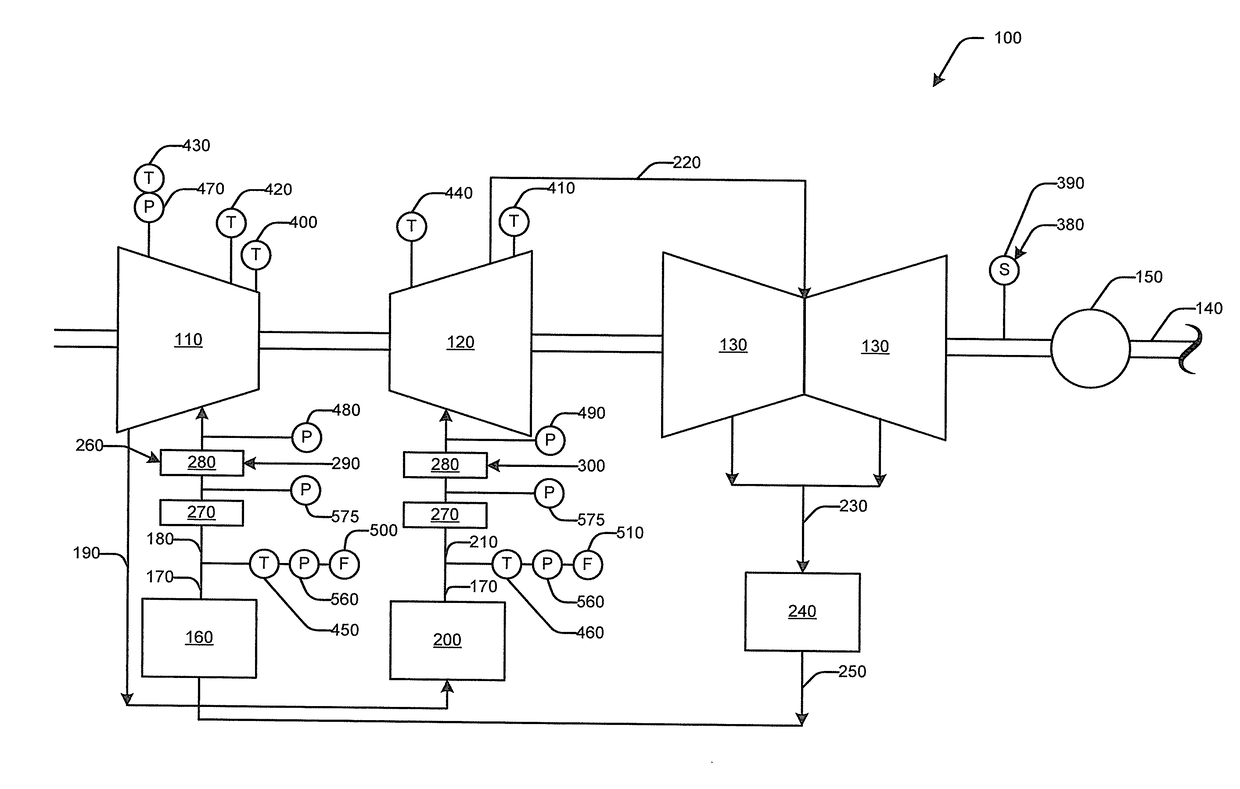
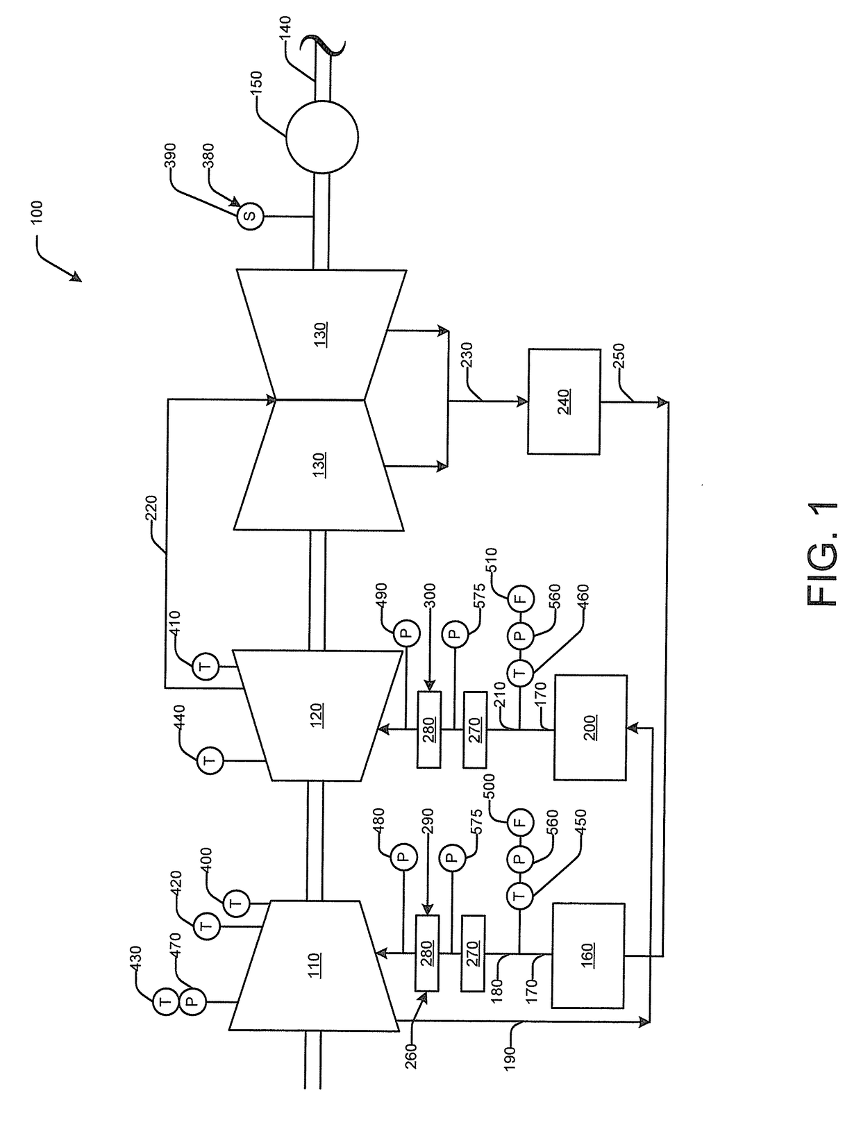
[0024]Referring now to the drawings, in which like numerals refer to like elements throughout the several views, FIG. 1 is a schematic diagram of a steam turbine system 100 as may be described herein. Generally described, the steam turbine system 100 may include a high pressure section 110, an intermediate pressure section 120, and a low pressure section 130. The high pressure section 110, the intermediate pressure section 120, and the low pressure section 130 may be positioned on and may drive a rotor shaft 140. The rotor shaft 140 also may drive a generator 150 for the production of electrical power or for other types of useful work. The steam turbine system 100 may have any suitable size, shape, configuration, or capacity.

[0025]A boiler 160 and the like may produce a flow of steam 170. The boiler 160 and the flow of steam 170 may be in communication with the high pressure section 110 via a high pressure line 180. The steam 170 may drive the high pressure section 110 and exit the ...


PUM


Abstract

The present application provides a method of evaluating valve conditions in a turbine by a data acquisition system. The method may include the steps of receiving a number of operating parameters from a number of sensors, wherein the operating parameters may include steam temperatures determined over time and steam pressure, determining a steam chemistry, a throttling history, and a piping material, determining a probability of valve erosion based upon the steam temperatures determined over time, the steam chemistry, the throttling history, and the piping material, and altering one or more of the operating parameters and/or initiating repair procedures based upon the determined probability.

Description

TECHNICAL FIELD[0001]The present application and resultant patent relate generally to monitoring and control systems for steam turbines and other types of turbomachinery and more particularly relate to a valve and actuator monitoring system for steam turbines and the like that provides continuous component and system status information, warnings, and corrections.BACKGROUND OF THE INVENTION[0002]A steam turbine converts the kinetic or thermal energy of pressurized steam into useful mechanical work. Generally described, the steam is created in a steam generator or a boiler, passes through control valves and stop valves into the sections, and drives a rotor assembly. The rotor assembly then in turn may drive a generator to produce electrical energy and the like. The control valves and the stop valves control the operation of the steam turbine by controlling the flow of the steam into the sections. A control valve typically controls or regulates the volumetric flow and / or the pressure o...

Claims


Application Information

Patent Timeline
IPC IPC(8): F01D21/00F01D17/20F01D17/14G01M15/14G01N17/00G05B19/406G05B23/02
CPCF01D21/003F01D17/20F01D17/145G01M15/14G01N17/00G05B2219/24001G05B23/0267F05D2220/31F05D2230/80F05D2270/54G05B19/406G06Q10/06F05D2270/80F05D2260/80G05B23/0289G05B23/0283
Inventor REIGL, MARTIN
Owner GENERAL ELECTRIC TECH GMBH
Why Eureka
Try Eureka