
Ultra-low-power design memory power reduction scheme

a memory power reduction and ultra-low-power design technology, applied in data processing power supply, instruments, high-level techniques, etc., can solve the problems of increasing power consumption, increasing memory access latency, and reducing the overall system performance, so as to reduce leakage power, reduce overall system performance, and increase memory access latency

Active Publication Date: 2018-03-08
QUALCOMM INC
View PDF3 Cites 16 Cited by
  • Summary
  • Abstract
  • Description
  • Claims
  • Application Information

AI Technical Summary

Benefits of technology

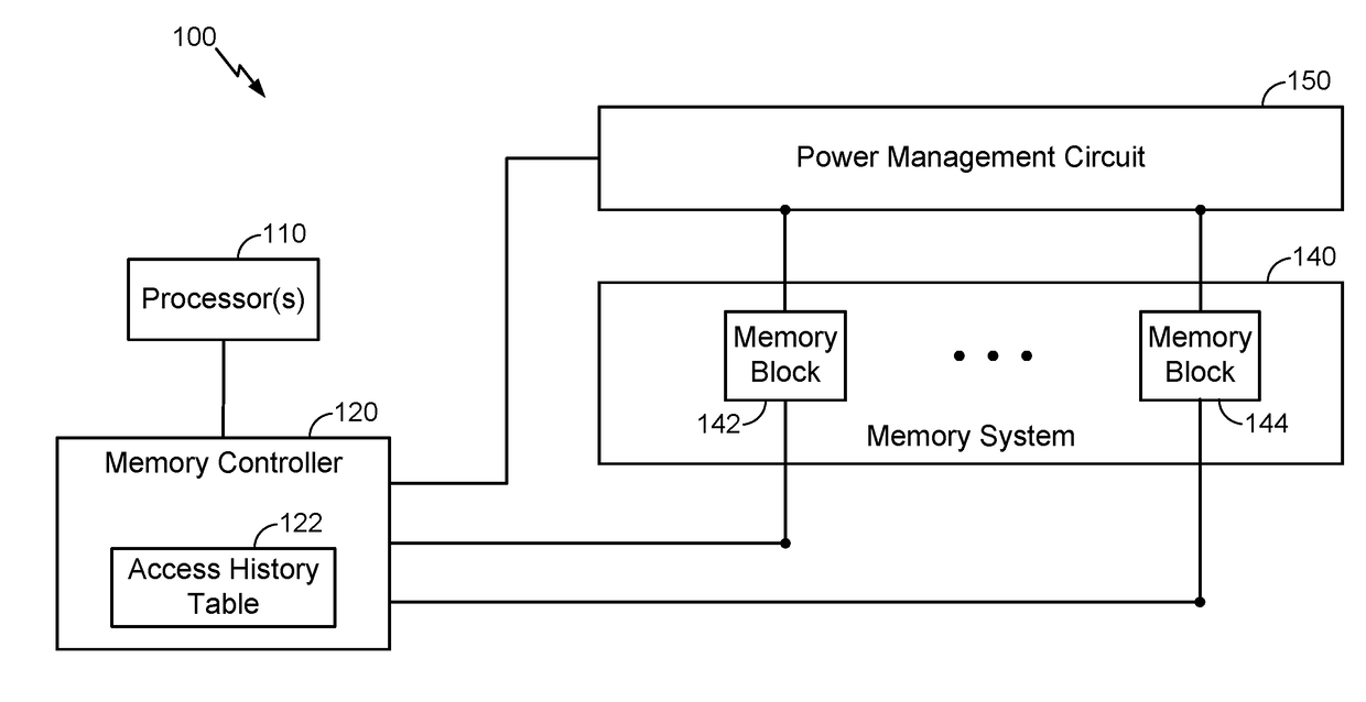
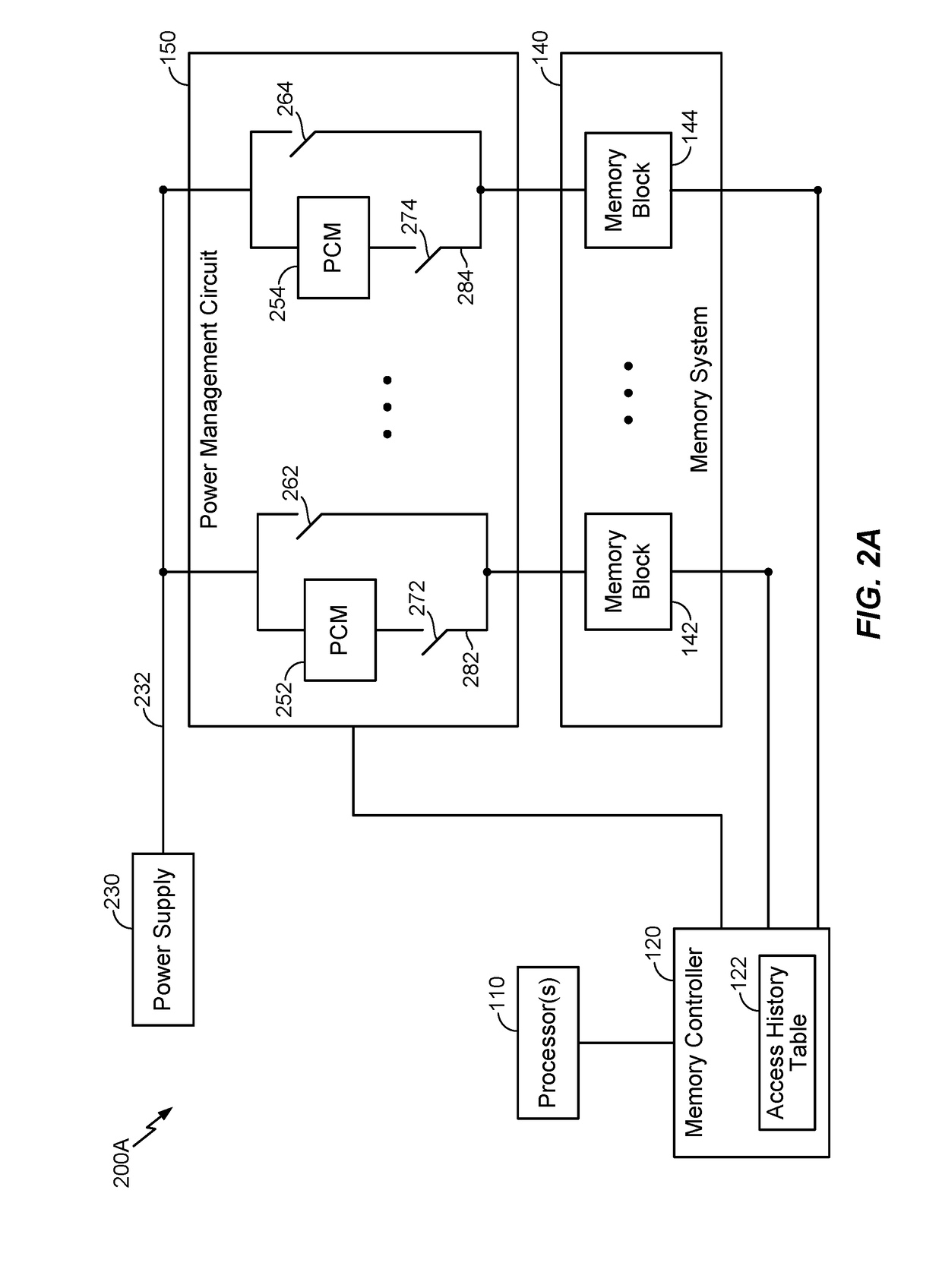
The patent describes a memory power reduction scheme that can manage power consumption without impacting performance. It involves manipulating power states of individual memory blocks that are not accessed, while only activating them when accessed. This helps reduce leakage power and improve system performance. The scheme also optimizes memory state transitions to achieve low power consumption and reduce access time penalties. Overall, the patent provides a technical solution for managing memory power consumption.

Problems solved by technology

Furthermore, because moving memory blocks into the low-leakage states and back to the active power state can take time (and power), which can increase memory access latency, lower overall system performance, and increase power consumption if state transitions are very frequent, the memory power reduction scheme described herein may have the flexibility to optimize memory state transitions to achieve low overall power and reduce access time penalties.

Method used


Image

  • Ultra-low-power design memory power reduction scheme
  • Ultra-low-power design memory power reduction scheme
  • Ultra-low-power design memory power reduction scheme

Examples


Embodiment Construction

[0022]Various aspects and embodiments are disclosed in the following description and related drawings to show specific examples relating to exemplary aspects and embodiments. Alternate aspects and embodiments will be apparent to those skilled in the pertinent art upon reading this disclosure, and may be constructed and practiced without departing from the scope or spirit of the disclosure. Additionally, well-known elements will not be described in detail or may be omitted so as to not obscure the relevant details of the aspects and embodiments disclosed herein.

[0023]The word “exemplary” is used herein to mean “serving as an example, instance, or illustration.” Any embodiment described herein as “exemplary” is not necessarily to be construed as preferred or advantageous over other embodiments. Likewise, the term “embodiments” does not require that all embodiments include the discussed feature, advantage or mode of operation.

[0024]The terminology used herein describes particular embod...


PUM


Abstract

The disclosure generally relates to a memory power reduction scheme that can flexibly transition memory blocks among different power states to reduce power consumption (especially with respect to leakage power) in a manner that balances tradeoffs between reduced power consumption and performance impacts. For example, according to various aspects, individual memory blocks may be associated with an access-dependent age, whereby memory blocks that are not accessed may be periodically aged. As such, in response to the age associated with a memory block crossing an appropriate threshold, the memory block may be transitioned to a power state that generally consumes less leakage power and has a larger performance penalty. Furthermore, one or more performance-related criteria may be defined with certain memory blocks to prevent and / or automatically trigger a transition to another power state.

Description

TECHNICAL FIELD[0001]The various aspects and embodiments described herein generally relate to managing power consumption in an on-die memory circuit, and more particularly, to a memory power reduction scheme that can flexibly transitions between different memory power states to achieve low overall power and reduced access time penalties.BACKGROUND[0002]Integrated circuit fabrication technology continually improves, and consequently, transistors continue to shrink in size. As such, more transistors and more complicated circuits can be fabricated on an integrated circuit die, or alternatively, on a smaller die to be used in a given circuit. Smaller transistor size also supports faster operating speeds and provides other benefits. For on-die memories (e.g., dynamic random access memory (DRAM)), a major issue with shrinking transistor size is standby power, as smaller transistor geometry results in higher electric fields, which stresses a transistor and causes oxide breakdown. Furthermo...

Claims


Application Information

Patent Timeline
Patent Type & Authority Applications(United States)
IPC IPC(8): G06F1/32
CPCG06F1/3296G06F1/3287G06F1/3225G06F1/3275G11C5/14G11C7/22G11C11/4074G11C2207/2227Y02D10/00Y02D30/50
Inventor SAMSON, GIBYAGHERA, PARIXIT LALJIBHAINEWHAM, ADAM EDWARD
Owner QUALCOMM INC
Learn More