
Apparatus for activating an electrically or electronically controlled appliance from an energy-saving passive state

a technology of electrically or electronically controlled appliances and actuators, which is applied in the direction of power management, instruments, high-level techniques, etc., can solve the problems of limited battery life time, small operating distance between the first and the second device, and little power consumption, so as to reduce the life time of the battery and the effect of large operation distan

Active Publication Date: 2018-03-08
MARQUARDT GMBH SCHLOSSTRASSE 16 7201 RIETHEIM-WEILHEIM 1 WEST GERMANY +1
View PDF3 Cites 1 Cited by
  • Summary
  • Abstract
  • Description
  • Claims
  • Application Information

AI Technical Summary

Benefits of technology

The present invention aims to address the problem of reducing the life time of a battery for a second device by allowing it to be deactivated for a significant amount of time, while only activating it during specific intervals. This reduces power consumption and allows for higher frequencies, which in turn increases the operation distance. The second device has a cyclic repeated receiving mode that simplifies the time controlling of the second device. By having a determined receiving time interval, the second device can receive a complete data protocol in a short time, minimizing power consumption. In some embodiments, signals from the first device are divided into blocks for higher data transmission security.

Problems solved by technology

Nevertheless this little power consumption is a limitation for the battery life time of the second device.
A disadvantage of such apparatus working with LF-transmitters is the small operating distance between the first and the second device.

Method used


Image

  • Apparatus for activating an electrically or electronically controlled appliance from an energy-saving passive state
  • Apparatus for activating an electrically or electronically controlled appliance from an energy-saving passive state
  • Apparatus for activating an electrically or electronically controlled appliance from an energy-saving passive state

Examples


Embodiment Construction

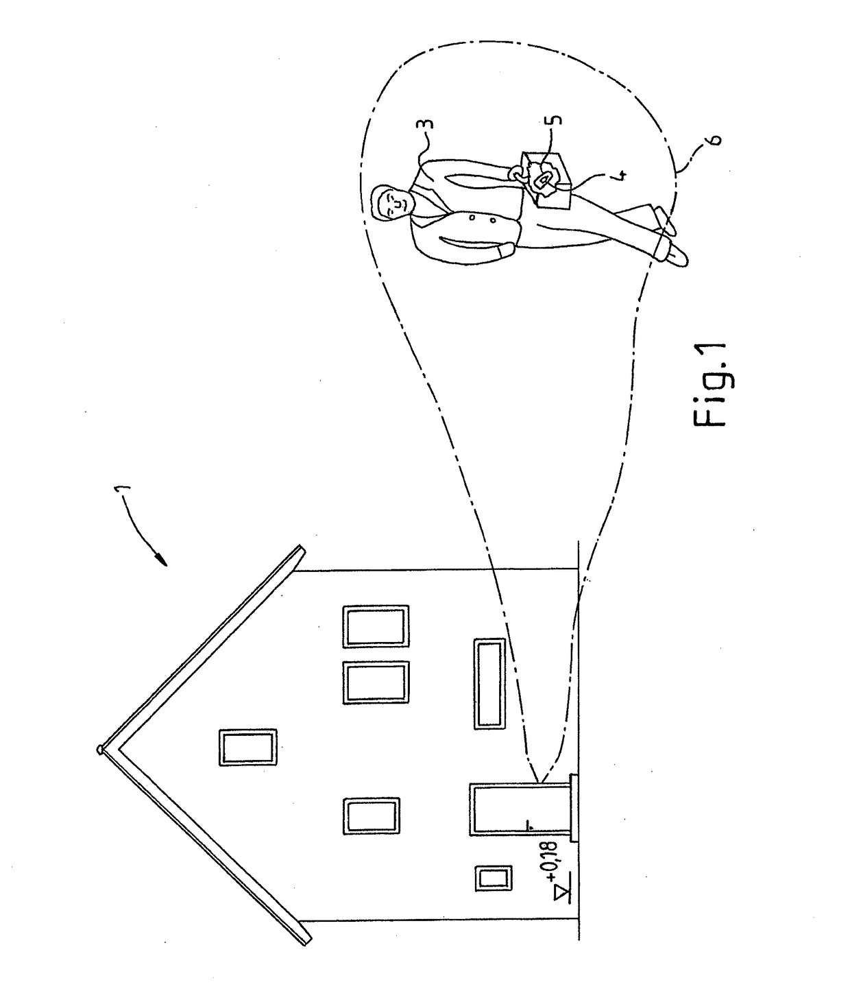
[0035]In FIG. 1 a building 1 is shown, in which a first device 2 having a transmitter is arranged.

[0036]An operator 3 is carrying a handbag with the second device 4 inside, especially the key 5. When the operator approaches to the building the operator and the car key 5 are coming into the operation distance 6 between the first device 2 and the second device 4.

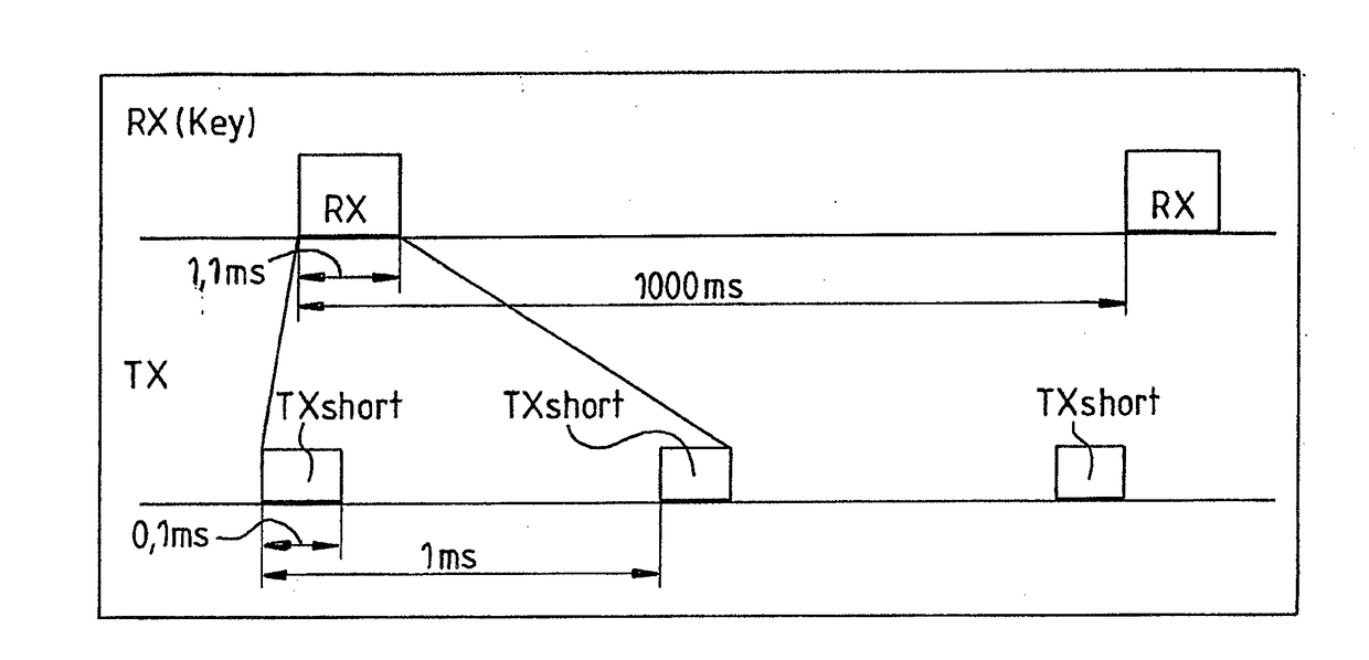
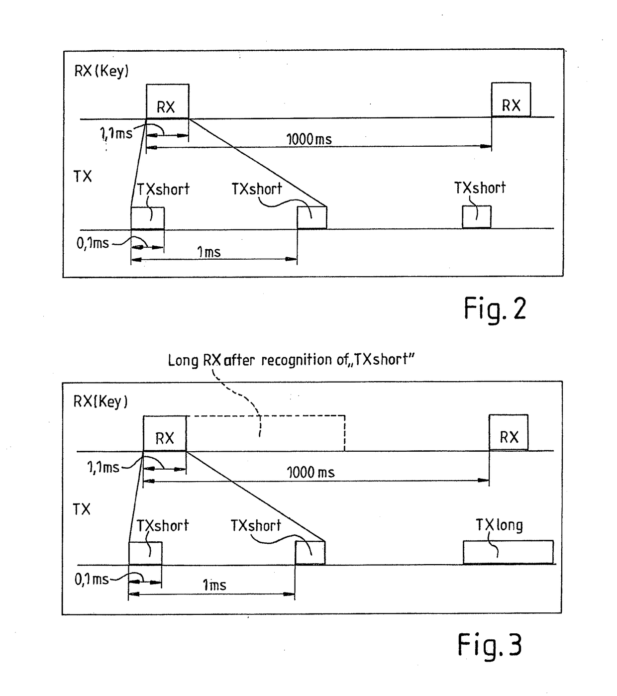
[0037]In FIG. 2 the first cycling repeated signal (TX short) of the first device (TX) is shown. In this embodiment the time interval for the first cyclic repeated signal (TX short) of the first device is 0.1 ms.

[0038]The first cycle time of the first cycled repeated signal (TX) is shown with 1 ms.

[0039]This means, that the first signal of the first device needs a certain power consumption for maintaining the short cycle time with a corresponding high repeating rate. This is no problem, because the first device with the corresponding transmitter is arranged in the building.

[0040]The key (or second device) has time controlled ac...


PUM


Abstract

An apparatus for activating an electrically or electronically controlled appliance from an energy-saving passive state, especially a locking system for locking and / or unlocking, in particular for an access and / or authorization and / or for other services for a wireless remote control, for controlling of front doors, for motor vehicles, or the like comprising a first device in the appliance and an associated second device designed in the type of an electronic key, an ID-transponder, a chip card or the like, wherein both devices for the intended operation have transmitters and / or receivers for electromagnetic signals is suggested which allows a large operation distance and a long battery lifetime of the second device. This is achieved in that the first device transmits a first cyclic repeated signal for the activation and / or authentication of the second device with a first data protocol within a first transmission time interval and with a first cycle time.

Description

CROSS REFERENCE TO RELATED APPLICATIONS[0001]This application is a continuation of International Application No. PCT / EP2016 / 055220 filed Mar. 11, 2016, which designated the United States, and claims the benefit under 35 USC §119(a)-(d) of German Application No. 10 2015 105 008.0 filed Mar. 31, 2015, the entireties of which are incorporated herein by reference.FIELD OF THE INVENTION[0002]The present invention relates to an apparatus for activating an electrically or electronically controlled appliance from an energy-saving passive state.BACKGROUND OF THE INVENTION[0003]Such apparatus are known for example as apparatus for locking and / or unlocking in particular for front doors, remote controls, car locking devices, etc. For example, in the document EP 1 867 535 B1 such an apparatus is disclosed.[0004]In a known apparatus, a first device is arranged in a basis object i.e. in a building, a motor vehicle, etc., which is able to activate a second device designed in the type of an electron...

Claims


Application Information

Patent Timeline
Patent Type & Authority Applications(United States)
IPC IPC(8): G06F1/32H04L29/06H04W12/06G07C9/00H04W52/02
CPCG06F1/3287H04L63/0853H04L63/0492H04W12/06G07C9/00111G07C9/00309H04W52/0216G07C2009/00507H04L67/12G07C2009/00373G07C2009/00396G07C2009/0038Y02D30/70G07C9/28
Inventor OBERGFELL, ROBERTWAGNER, SASCHAHOFINGER, MATTHIAS
Owner MARQUARDT GMBH SCHLOSSTRASSE 16 7201 RIETHEIM-WEILHEIM 1 WEST GERMANY
Learn More