
X-ray tube with gridding electrode

a radiation source and x-ray tube technology, applied in the direction of electrical discharge tubes, basic electric elements, electrical equipment, etc., can solve the problems of reducing image quality, reducing the life of x-ray tubes, and x-ray tube damag

Active Publication Date: 2018-03-08
GENERAL ELECTRIC CO
View PDF4 Cites 4 Cited by
  • Summary
  • Abstract
  • Description
  • Claims
  • Application Information

AI Technical Summary

Benefits of technology

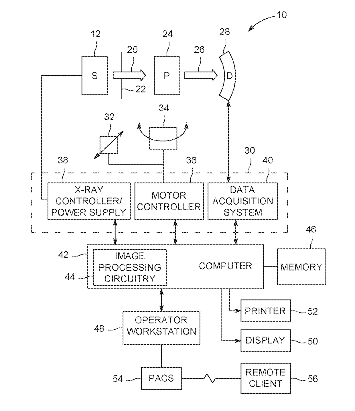
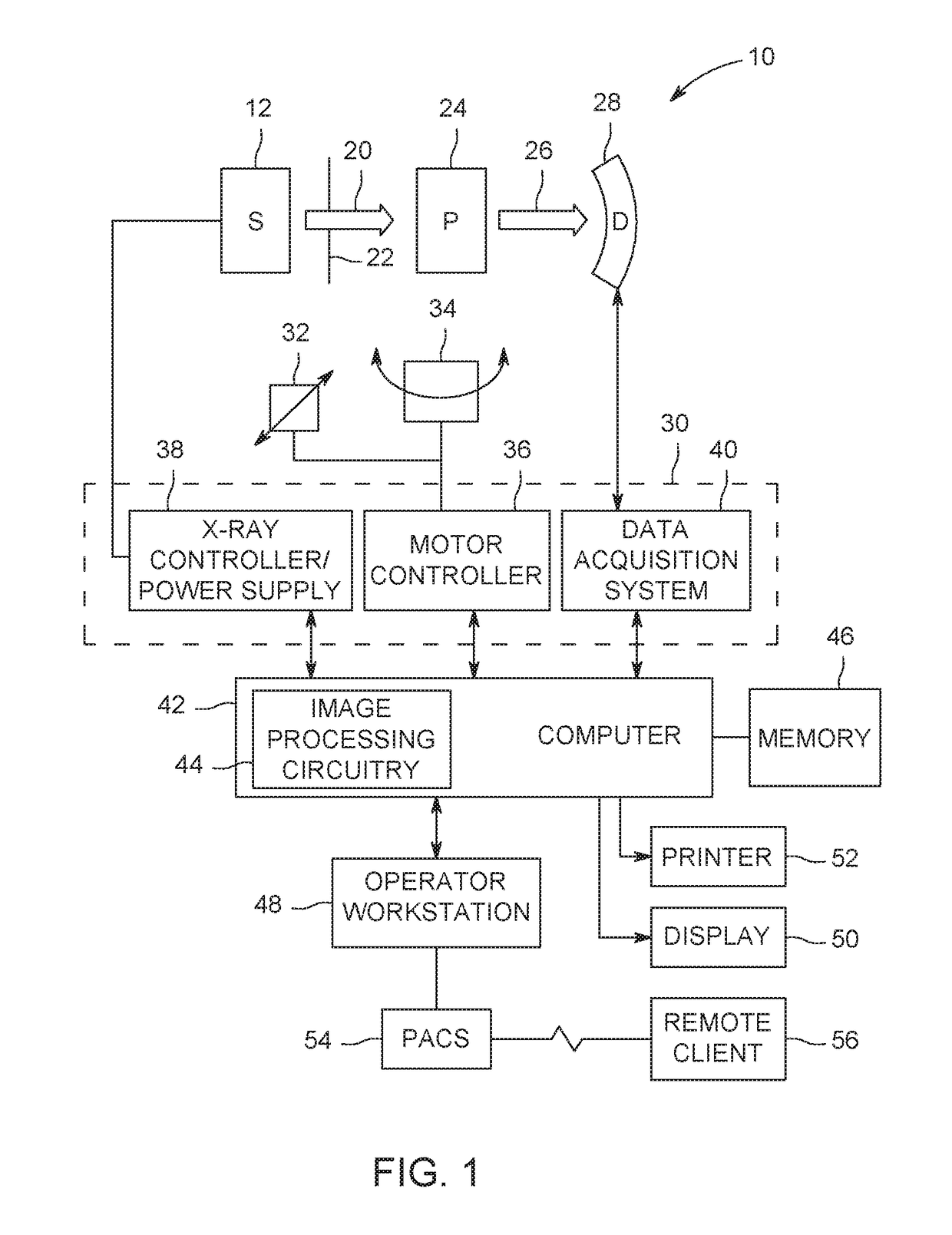
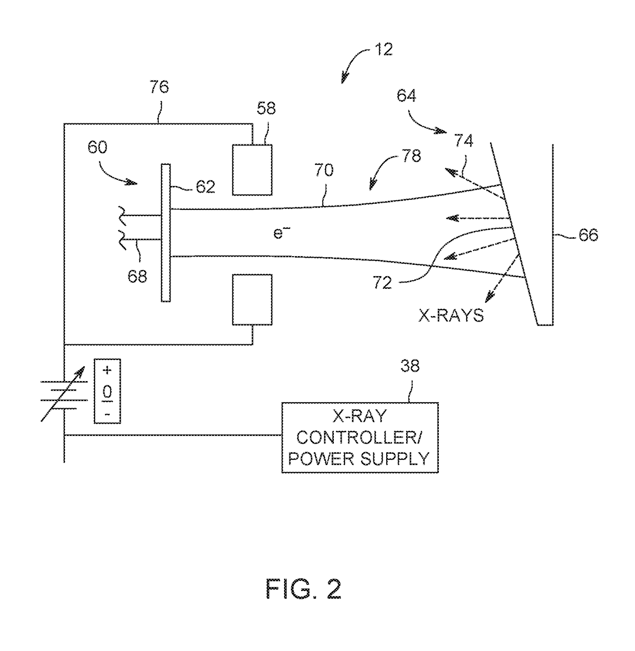
The patent text describes an X-ray imaging system that includes an X-ray tube, with a gridding electrode that controls the electron beam in a way that synchronizes with dynamic focal spot modes, which are important for medical applications like angiography. This allows for improved image quality and reduced patient X-ray exposure to radiation. Additionally, the patent describes a method for making the X-ray tube by assembling it with a specific gridding electrode and power supply, and a controller to synchronize the gridding with planned transitions during a dynamic focal spot mode. These technical effects improve the performance and reliability of X-ray imaging systems.

Problems solved by technology

These transitions or switches during the dynamic focal spot mode may result in damage to the X-ray tube due to focal spot instability or variation and, thus, a shortened X-ray tube life.
For example, too large an electron beam (e.g., resulting in damage to beam pipe or other internal apertures thru which the electron beam travels en route to the target) or too small an electron beam (e.g., resulting in target overheating) may result in X-ray tube damage.
In addition, focal spot instability may result in reduced image quality due to the acquisition of focal spot artifacts.
Further, in an effort to avoid exceeding a temperature limit of the target (e.g., anode) due to overheating or re-heating during the dynamic focal spot mode, the beam power and, thus, the X-ray flux may be limited.

Method used


Image

  • X-ray tube with gridding electrode
  • X-ray tube with gridding electrode
  • X-ray tube with gridding electrode

Examples


Embodiment Construction

[0019]One or more specific embodiments will be described below. In an effort to provide a concise description of these embodiments, all features of an actual implementation may not be described in the specification. It should be appreciated that in the development of any such actual implementation, as in any engineering or design project, numerous implementation-specific decisions must be made to achieve the developers' specific goals, such as compliance with system-related and business-related constraints, which may vary from one implementation to another. Moreover, it should be appreciated that such a development effort might be complex and time consuming, but would nevertheless be a routine undertaking of design, fabrication, and manufacture for those of ordinary skill having the benefit of this disclosure.

[0020]When introducing elements of various embodiments of the present invention, the articles “a,”“an,”“the,” and “said” are intended to mean that there are one or more of the ...


PUM


Abstract

An X-ray tube is provided. The X-ray tube includes an electron beam source including a cathode configured to emit an electron beam. The X-ray tube also includes an anode assembly including an anode configured to receive the electron beam and to emit X-rays when impacted by the electron beam. The X-ray tube further includes a gridding electrode disposed about a path of the electron beam between the electron beam source and the anode assembly. The gridding electrode, when powered at a specific level, is configured to grid the electron beam in synchronization with planned transitions during a dynamic focal spot mode.

Description

BACKGROUND[0001]The subject matter disclosed herein relates to X-ray tube radiation sources and more particularly to X-ray tube radiation sources having gridding electrodes.[0002]In imaging systems, X-ray tubes are used in projection X-ray systems, fluoroscopy systems, tomosynthesis systems, and computer tomography (CT) systems as a source of X-ray radiation. Typically, the X-ray tube includes a cathode and an anode. The cathode emits a stream of electrons in response to heat resulting from an applied electrical current via the thermionic effect. The anode includes a target that is impacted by the stream of electrons. The target, as a result, produces X-ray radiation and heat. Such systems are useful in medical contexts, but also for parcel and package screening, part inspection, various research contexts, and so forth.[0003]The radiation traverses a subject of interest, such as a human patient, and a portion of the radiation impacts a detector or photographic plate where the image ...

Claims


Application Information

Patent Timeline
Patent Type & Authority Applications(United States)
IPC IPC(8): H01J35/14H01J35/06H01J35/08H05G1/10
CPCH01J35/14H05G1/10H01J35/08H01J35/06H05G1/085H05G1/58H01J35/153
Inventor UTSCHIG, MICHAEL JOHNWIEDMANN, UWEDE MAN, BRUNO KRISTIAAN BERNARDLEMAITRE, SERGIOFRONTERA, MARK ALANCAIAFA, ANTONIOFAN, JIAHUABUDDE, ADAM
Owner GENERAL ELECTRIC CO
Learn More