Seal arrangement for a mid turbine frame of a gas turbine

a gas turbine and frame technology, applied in the direction of bearings, shafts, leakage prevention, etc., can solve the problems of fretting at the contact sites of piston rings, bearing sleeves, ducts,

Active Publication Date: 2018-03-22
MTU AERO ENGINES GMBH
View PDF2 Cites 0 Cited by
  • Summary
  • Abstract
  • Description
  • Claims
  • Application Information

AI Technical Summary

Benefits of technology

[0003]The object of the invention is to provide a seal a

Problems solved by technology

In particular, fretting may occur at the contact sites between piston ring, duct, and bearing sleeve during operation of t

Method used


Image

  • Seal arrangement for a mid turbine frame of a gas turbine
  • Seal arrangement for a mid turbine frame of a gas turbine
  • Seal arrangement for a mid turbine frame of a gas turbine

Examples


Embodiment Construction

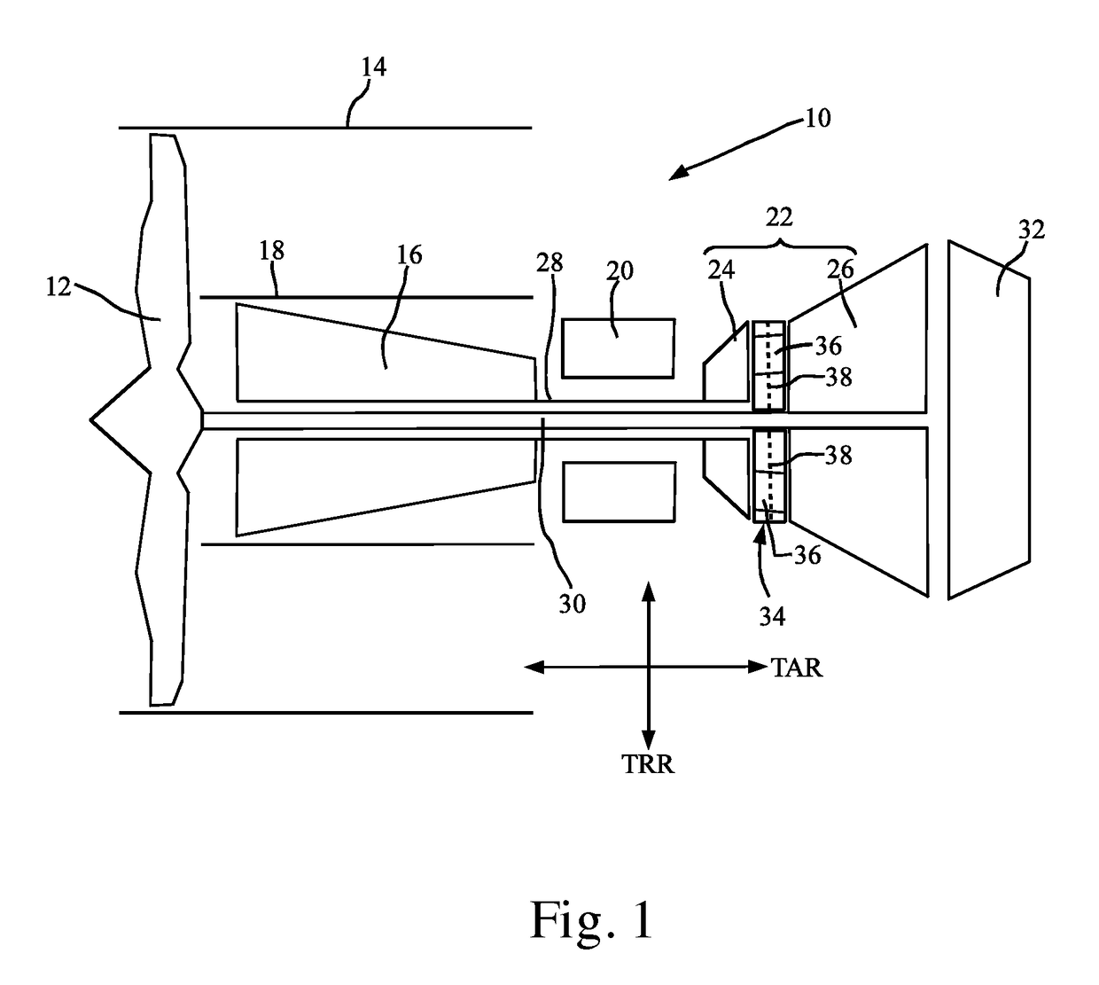
[0015]Heavily simplified and schematically FIG. 1 shows the layout of a gas turbine 10, especially an aircraft gas turbine (e.g., a turbofan engine). The gas turbine 10 comprises a fan 12, which is surrounded by a roughly indicated casing 14. In an axial direction TAR of the gas turbine 10, next to the fan 12 is connected a compressor 16, which is taken up in a roughly indicated inner housing 18, and may be designed as a single-stage or multi-stage type. Next to the compressor 16 is connected the combustion chamber 20. Hot gas flowing out from the combustion chamber 20 then flows through the adjoining turbine 22, which may be designed as a single-stage or multi-stage type. In the present example, the turbine 22 comprises a high-pressure turbine 24 and a low-pressure turbine 26. A hollow shaft 28 connects the high-pressure turbine 24 to the compressor 16, especially a high-pressure compressor, so that they rotate together. Another interior shaft 30 connects the low-pressure turbine 2...


PUM


Abstract

The seal arrangement for a mid turbine frame of a gas turbine, especially an aircraft gas turbine, includes a tubular fluid duct, especially an oil duct, which extends along an axial direction, a bearing sleeve surrounding the fluid duct radially outside and in the peripheral direction, and at least one seal ring arranged between fluid duct and bearing sleeve in the radial direction, this ring being arranged around the fluid duct. The seal ring is taken up at least partly in a groove provided in the bearing sleeve.

Description

BACKGROUND OF THE INVENTION[0001]The present invention relates to a seal arrangement for a mid turbine frame of a gas turbine, especially an aircraft gas turbine, with a tubular fluid duct, especially an oil duct, which extends along an axial direction, a bearing sleeve surrounding the fluid duct radially outside and in the peripheral direction, and at least one seal ring arranged between fluid duct and bearing sleeve in the radial direction, this seal ring being arranged around the fluid duct. By the axial direction is meant here the principal direction of extension of the fluid duct.[0002]In a mid turbine frame, oil ducts are led through struts in order to supply a bearing, the struts extending through an annular channel which conveys hot gas. These ducts comprise a so-called fixed bearing and a so-called floating bearing. The floating bearing of the ducts is designed so that movements in the axial direction of the tubular ducts are permitted during operation of the gas turbine. I...

Claims


Application Information

Patent Timeline
IPC IPC(8): F01D11/00F16J15/34F01D9/06
CPCF01D11/003F16J15/3464F01D9/065F16C33/74F01D25/16F01D25/18F16J15/441F16C2360/23F16C17/02F16C17/22
Inventor BOKHORST, WILLEMMORITZ, FABIAN
Owner MTU AERO ENGINES GMBH
Why Eureka
Try Eureka