A mounting medium for embedding a sample material and a method of mounting a sample material in a mounting medium

a technology of mounting medium and sample material, which is applied in the direction of chemistry apparatus and processes, instruments, transportation and packaging, etc., can solve the problems of difficult and often time-consuming tasks, and the sample mounting process is still a time-consuming operation, so as to reduce heat transfer gradients, increase thermal energy transfer, and increase heat conductivity

Active Publication Date: 2018-03-29
STRUERS
View PDF0 Cites 8 Cited by
  • Summary
  • Abstract
  • Description
  • Claims
  • Application Information

AI Technical Summary

Benefits of technology

[0035]The present invention seeks in general to reduce cycle times of hot mounting processes for sample materials. Moreover, the present invention seeks to set forth a granular mounting medium which allows for a reduction in cycle times of hot mounting processes while also being cost-effective and easy to produce.
[0037]Tests has shown that the cycle times, i.e. heating and cooling, may be lowered from about 5 minutes to about 3½ minutes without imposing significant temperature gradients to or throughout the mounting medium.
[0038]The mounting medium according to the first aspect of the present invention is configured, or composed, such that the mounting medium allows for lowering the heat transfer gradients. This will result in increased thermal energy transfer, or increased heat conductivity, between the walls of the mould and the mounting.
[0039]Increased heat conductivity of the mounting medium reduces the time required for mounting the sample material as the time required for uniformly heating the batch to a certain temperature is reduced significantly.
[0056]optimum heat conductivity of the mounting medium and thereby relatively small temperature gradients during heating and / or cooling of the mounting medium. The extraordinary high heat conductivity is obtained as aluminium particles, during moulding / sintering, compile around the granular resin and thereby form internal bridges within the moulded mounting media. In the abovementioned mounting media named ConduFast, where the metal filler is iron, the metal particles tend not to compile around the resin and, consequently, i.e. no internal metal bridges within the moulded mounting media are formed. The graphite in ConduFast forms around the acrylic particles thereby establishing electrical connection through the mounting medium via the iron particles,
[0058]density corresponding to the density of the resin which inter alia may constitute acryl or plastic. Corresponding densities to prevent segregation of the blend and facilitates formation of internal bridges,

Problems solved by technology

Preparing sample materials such as materialographic and / or metallographic samples for analysis such as for microscopy or SEM for hardness testing or image analysis, is a challenging and often time consuming task; inter alia as each sample must be fixed by moulding in an often modular sample holder in order to facilitate not only the analysis, but also the preparation of the sample material for the analysis.
The sample mounting process is, despite the sophisticated techniques, still a time consuming operation; especially since cycle times required by any steps of heating and / or cooling are limited significantly by the mounting medium's ability to transfer heat into and out from the embedding matrix.
This, however, is undesirable inter alia as:large temperature gradients in effect compromise the integrity of the mounting medium, andlarge temperature gradients cause the mounting media to sinter with a less than an adequate or suitable rate to give a homogeneous sintering of the matrix within short cycle times.

Method used


Image

  • A mounting medium for embedding a sample material and a method of mounting a sample material in a mounting medium
  • A mounting medium for embedding a sample material and a method of mounting a sample material in a mounting medium
  • A mounting medium for embedding a sample material and a method of mounting a sample material in a mounting medium

Examples


Embodiment Construction

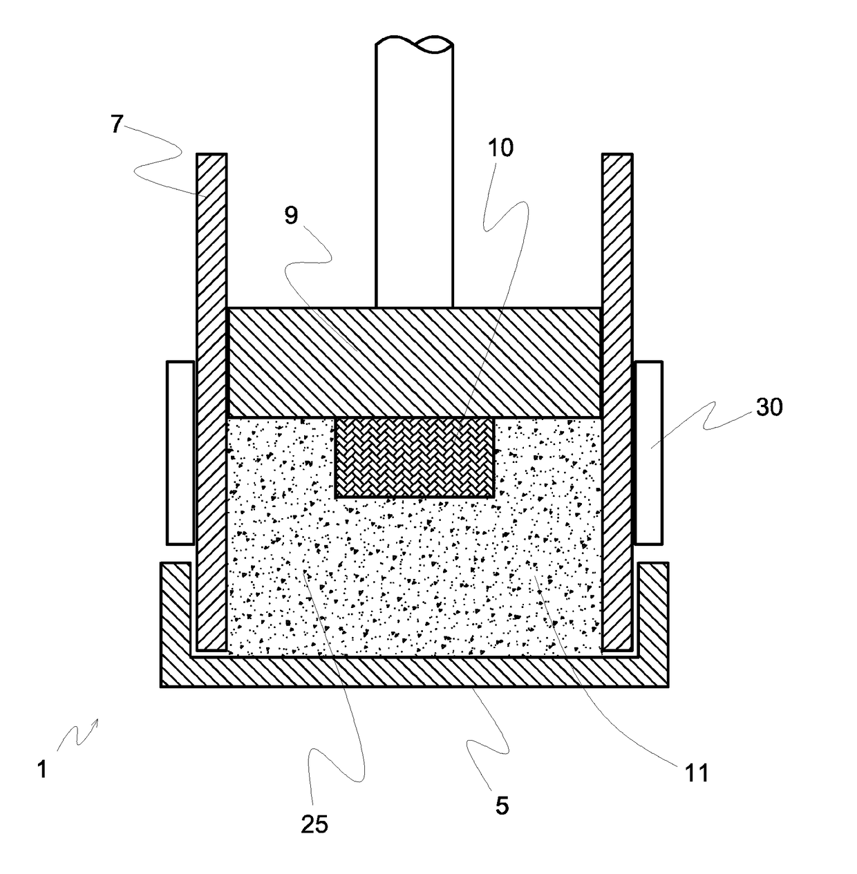
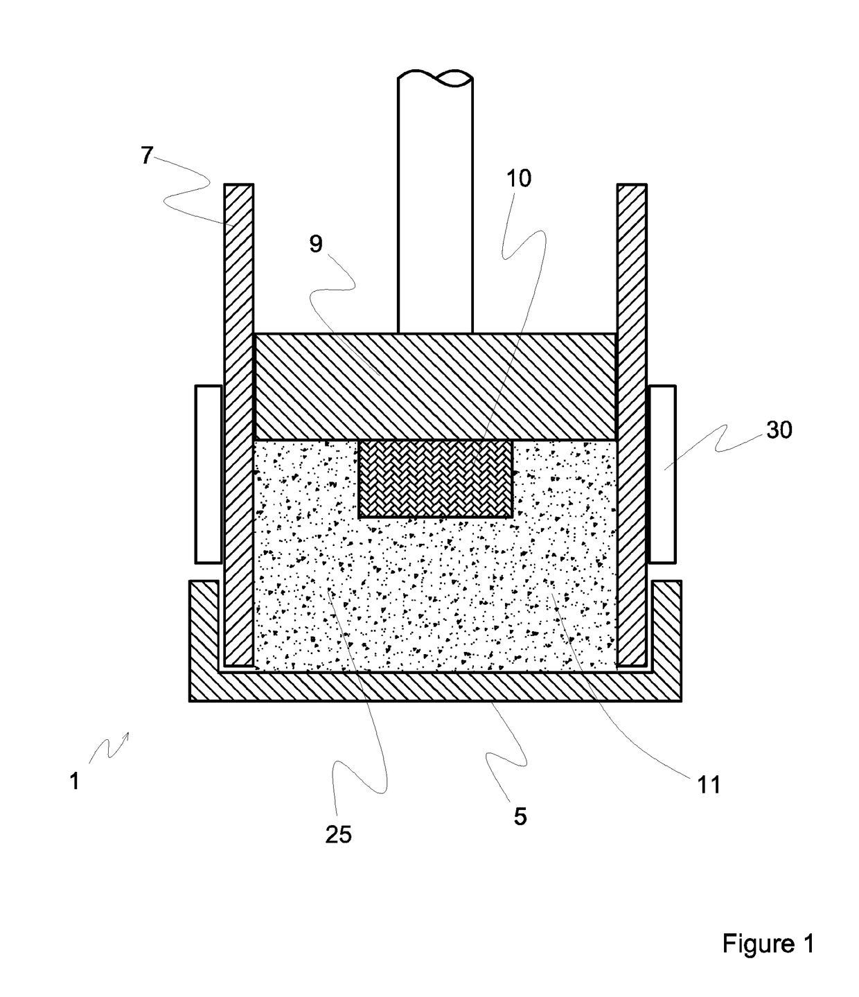
[0069]The present invention will in the below be explained in more detail with reference to the schematic FIGS. 1, 2 and 3.

[0070]FIGS. 1 and 3 show a compression mould 1 including a lid or cover 5, walls 7 which may be embodied as a cylinder, and pressing means 9. The pressing means 9 may, as shown, be embodied as a ram.

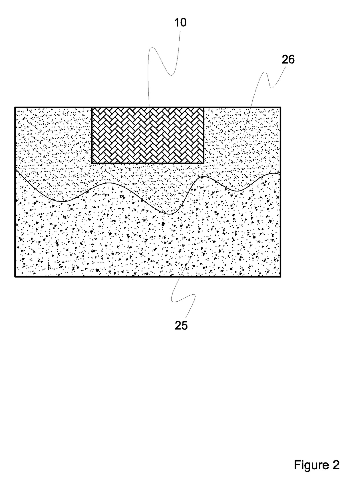
[0071]The walls 7, the lid 5 and the pressing means 9 together define a cavity 11 configured for receiving a sample material 10 and the mounting medium 25, 26 in accordance the present invention.

[0072]Temperature regulating means 30, i.e. heating and / or cooling means 30, is in the depicted embodiments according to FIGS. 1 and 3 shown as means encircling the walls 7 or the compression mould 1.

[0073]In the embodiment according to FIG. 1, a mounting medium 25 is filled in the cavity 11 and a sample material 10 is arranged inside the cavity 11 and in the mounting medium 25 such that an upper face of the sample material 10 is in level with the upper face of the mounting m...


PUM


Abstract

A method of embedding a sample material in a mounting medium with reduced cycle times and a mounting medium for embedding a sample material.The method includes the steps of:preparing a granular mounting medium by blending a granular resin and a granular filler,placing a sample material and said granular mounting medium in a moulding cavity,followed by the steps of:heating, for a first period of time, said moulding cavity including said granular mounting medium thereby producing a sintering mounting medium,cooling, for a second period of time, said moulding cavity including said mounting medium thereby producing a solid mounting medium embedding said sample material.

Description

[0001]The present invention relates, according to a first aspect, to a granular mounting medium for embedding or mounting a sample material.[0002]According to a second aspect, the present invention relates to a method of mounting a sample material in a mounting medium.[0003]According to a third aspect, the present invention relates to a method of preparing a granular mounting medium for embedding or mounting a sample material.[0004]A granular material typically is a conglomeration of discrete solid particles. Powders are a special class of granular materials due to their small particle size. Hence, the expression “granular”, in the context of the present disclosure, also refers to powders as such.[0005]The term “metallic” throughout this specification refers to a material having metal like character and properties which are associated with the elements classified as metals in the periodic table.[0006]The term “sintering” throughout this specification refers to a process of compactin...

Claims


Application Information

Patent Timeline
Patent Type & Authority Applications(United States)
IPC IPC(8): G01N1/36C09K5/14C08K3/08B22F3/16B22F7/02
CPCG01N1/36C09K5/14C08K3/08B22F3/16B22F7/02G01N2001/364C08K2003/0812C08K2201/005C08K2201/001B22F2301/052B22F2304/10C22C1/05B22F2003/1042B22F2998/10B22F2999/00B22F3/10B22F2203/11B22F1/052C22C1/0416B22F1/068B22F1/10B22F3/02B22F3/004
Inventor ODING, PER BUUS
Owner STRUERS
Why Eureka
Try Eureka