Time-to-digital converter with phase-scaled course-fine resolution

a time-to-digital converter and resolution technology, applied in the field of precision time measurement, can solve the problems of cost and power perspective, difficult detection, etc., and achieve the effects of high speed, easy detection, and simplified phase measurement encoding

Active Publication Date: 2018-03-29
MICROSEMI SEMICON
View PDF0 Cites 22 Cited by
  • Summary
  • Abstract
  • Description
  • Claims
  • Application Information

AI Technical Summary

Benefits of technology

[0015]When compared with a Vernier-ring TDC consisting of the same number of delay elements, embodiments of the invention make the encoding of the phase measurement simpler due to the fact that only the number of passes of the leading signal through the looped delay line need to be counted. This can be done in a simple counter, whereas in the prior art it was necessary to save the state of entire ring in internal memory for every pass through the ring so as to permit the state of the memory to be determined when the triggering signal arrived. By contrast, in the present invention the simple counter counts the number of passes through the ring, making it necessary only to encode that state of one pass, which is the last pass before the triggering signal arrives. To save all these states (and there can be many depending on how large a phase detection range is supported, i.e. how many times the signal passes through the ring before the triggering signal arrives), a large amount of internal memory that operates at high speed is required. This is very costly from chip area and power perspective.
[0016]Moreover, with a prior art Vernier ring it is not easy to detect whether the pass is odd or even pass, requiring additional detection complexity or double the number of elements (half for odd and half for even passes), which again implies a larger area. As a result, Vernier ring structures typically run at s lower reference speed, which allows the present invention to gain a couple of dB (2 to 3) by simply running at higher reference frequencies.
[0017]In addition to allowing simple encoding logic, and therefore lower area and power implementation, embodiments of the invention can support higher reference frequencies for a given technology, directly contributing to better system performance by over 5 dB.
[0018]In one embodiment the phase regulator can be combined with an arbiter to play a secondary role as a moderate resolution TDC. Such an embodiment can offer a 3-level (coarse / moderate / fine) resolution. The power consumption can be reduced by an order of magnitude compared to a conventional Vernier ring TDC.
[0019]Embodiments of the invention make use of an RRD (reference-retimed-by-DCO) signal as the triggering signal and the reference signal itself as the leading signal. The edge of the RRD signal always occurs after the edge of the REF signal, so it can be used as the trigger signal. This avoids the need for an extra logic circuit that is required for traditional TDC solutions that do not make use of the RRD signal to identify which signal comes first and which signal comes second, and then to route first signal as data and route second signal as trigger data.
[0020]TDCs in accordance with the invention may include a coordinated-determination evaluator to make the final arithmetic determination of moderate resolution output (QM) and the fine resolution output (QR) simpler and faster. The coordinated-determination evaluator also separates true transitions from fake transitions.

Problems solved by technology

This is very costly from chip area and power perspective.
Moreover, with a prior art Vernier ring it is not easy to detect whether the pass is odd or even pass, requiring additional detection complexity or double the number of elements (half for odd and half for even passes), which again implies a larger area.

Method used


Image

  • Time-to-digital converter with phase-scaled course-fine resolution
  • Time-to-digital converter with phase-scaled course-fine resolution
  • Time-to-digital converter with phase-scaled course-fine resolution

Examples


Embodiment Construction

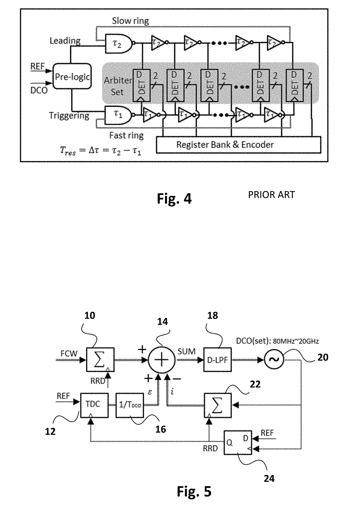
[0036]FIG. 5 is a schematic diagram of a typical digital phase-locked loop (DPLL). The accumulator 10 receives a frequency control word FCW as one input and a reference-retimed-by DCO input (RRD) from TDC 12, which compares the output of the DPLL with a reference source REF. The generation of the RRD signal is described below. The remaining components of the DPLL are the adder 14, divider 16, digital low pass filter 18, digitally controlled oscillator 20, accumulator 22, and flip-flop 24. The digital PLL ideally requires the TDC 12 to perform over a wide phase (time) detection range, have a fine resolution, have a low power consumption while occupying a compact chip area, and allow for a high reference frequency REF.

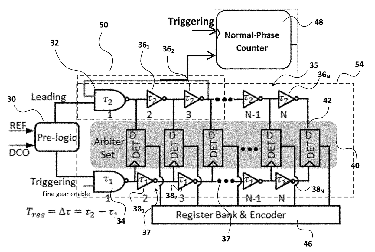
[0037]FIG. 6 illustrates the principles of a phase-scaled Vernier TDC in accordance with a basic embodiment of the invention. This embodiment employs a partial-ring in a slow delay chain 35. A pre-logic input module 30 receives as inputs a digitized reference signal REF ...


PUM


Abstract

A time-to-digital converter (TDC) measures a time interval ΔTTot between a leading signal and a triggering signal. A phase regulator incorporates a looped delay line to create pre-defined sub-intervals TNOR determined by the length of the delay line. The phase regulator has an input receiving the leading signal such that the leading signal loops around the delay line. A counter for counting the number of times m the leading signal loops around the delay line before said triggering signal arrives to obtain a coarse measurement of the time interval defined in terms of the sub-intervals TNOR. A Vernier core for measures a residual time interval TR where TR=ΔTTot−mTNOR to obtain a value for the time interval ΔTTot. The TDC uses simpler encoding logic with reduced power consumption and phase noise performance better than 5 dB.

Description

CROSS REFERENCE TO RELATED APPLICATION[0001]This application claims the benefit under 35 USC 119(e) of U.S. Provisional Application No. 62 / 398,693, filed Sep. 23, 2016, the contents of which are herein incorporated by reference.FIELD OF THE INVENTION[0002]This invention relates to the field of precision time measurement, and in particular to a precision time-to-digital converter.BACKGROUND OF THE INVENTION[0003]Time-to-Digital converters (TDCs) convert time intervals into a digital representation. There is a practical limit on the frequency of a master clock that can be used to measure time intervals. TDCs are primarily concerned with measuring time intervals between clock pulses of a master clock so as to offer a resolution better than would determined by the period of the master clock alone. TDCs have a number of applications, for example, in the field of particle physics, but an important application is the all-digital phase-locked loop (ADPLL), where they are used as phase detec...

Claims


Application Information

Patent Timeline
Patent Type & Authority Applications(United States)
IPC IPC(8): G04F10/00
CPCH03M1/1009G04F10/005H03M1/125H03M1/502
Inventor WANG, TUOXINROGERS, JOHN WILLIAM MITCHELLMITRIC, KRSTESITU, GUOHUI
Owner MICROSEMI SEMICON
Why Eureka
Try Eureka