
Ac-dc single-inductor multiple-output LED drivers

Active Publication Date: 2018-03-29
VERSITECH LTD
View PDF3 Cites 15 Cited by
  • Summary
  • Abstract
  • Description
  • Claims
  • Application Information

AI Technical Summary

Benefits of technology

The patent describes a design for LED lighting that uses a single DC-DC converter to control multiple LED strings. The design simplifies the driver circuit and reduces costs while also allowing for individual control and balancing of current across the LED strings. The driver is also designed to improve the power factor and stability of the lighting network. Overall, the design provides a more efficient and scalable solution for LED lighting applications.

Problems solved by technology

However, the existing topologies for driving multiple LED strings are very inefficient.
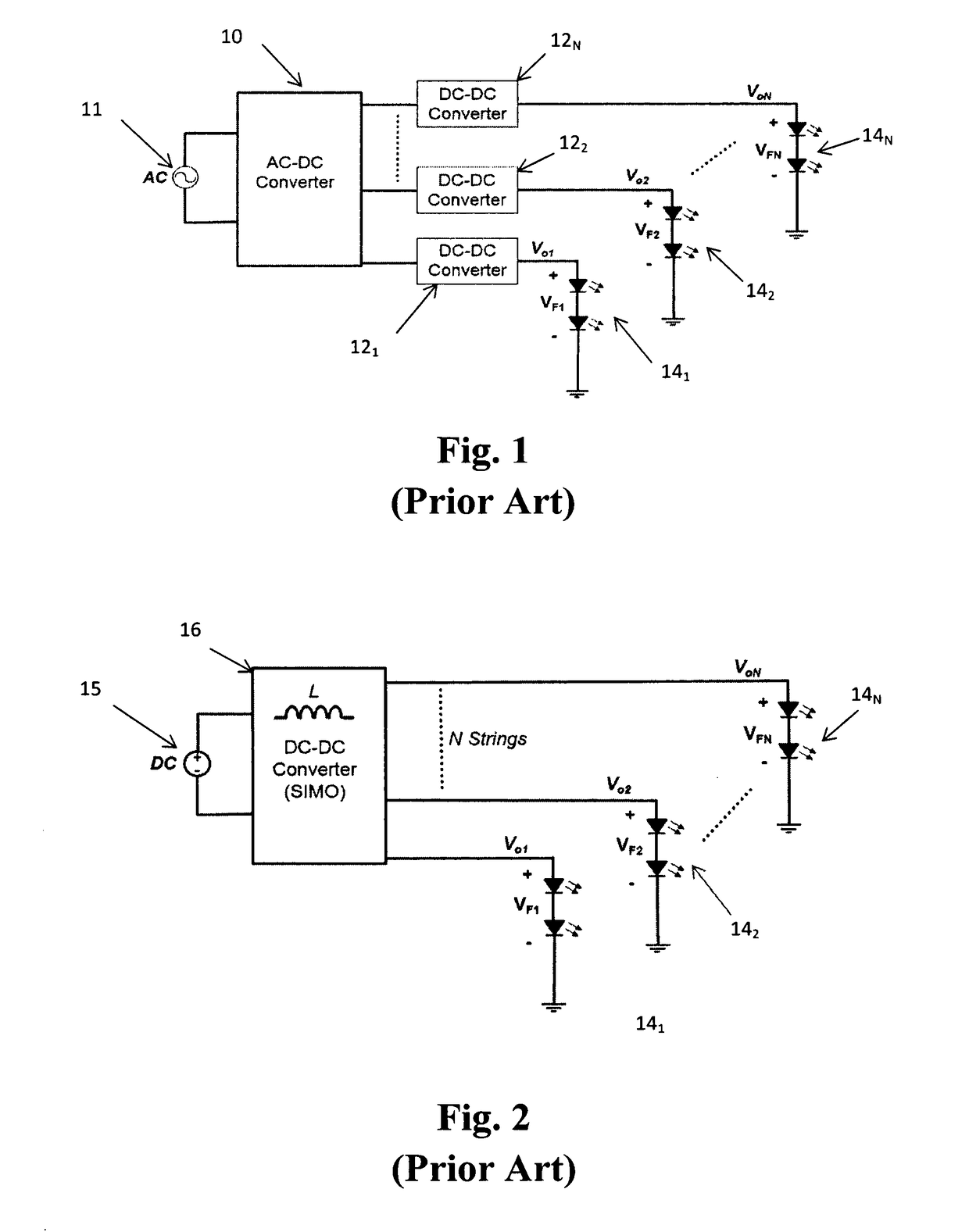
They typically require multiple DC-DC converters and complex circuitry which increase the total component count and overall bill of material costs.
The cost and complexity increases with the total number of LED strings.
Existing topologies for driving multiple LED strings are very inefficient.
They typically require multiple DC-DC converters and complex circuitry, which increase the total component count and overall material costs.
Further, the cost and complexity increases with the total number of LED strings.
This will inevitably lead to higher costs and a larger form factor as the total number of LED strings increases.
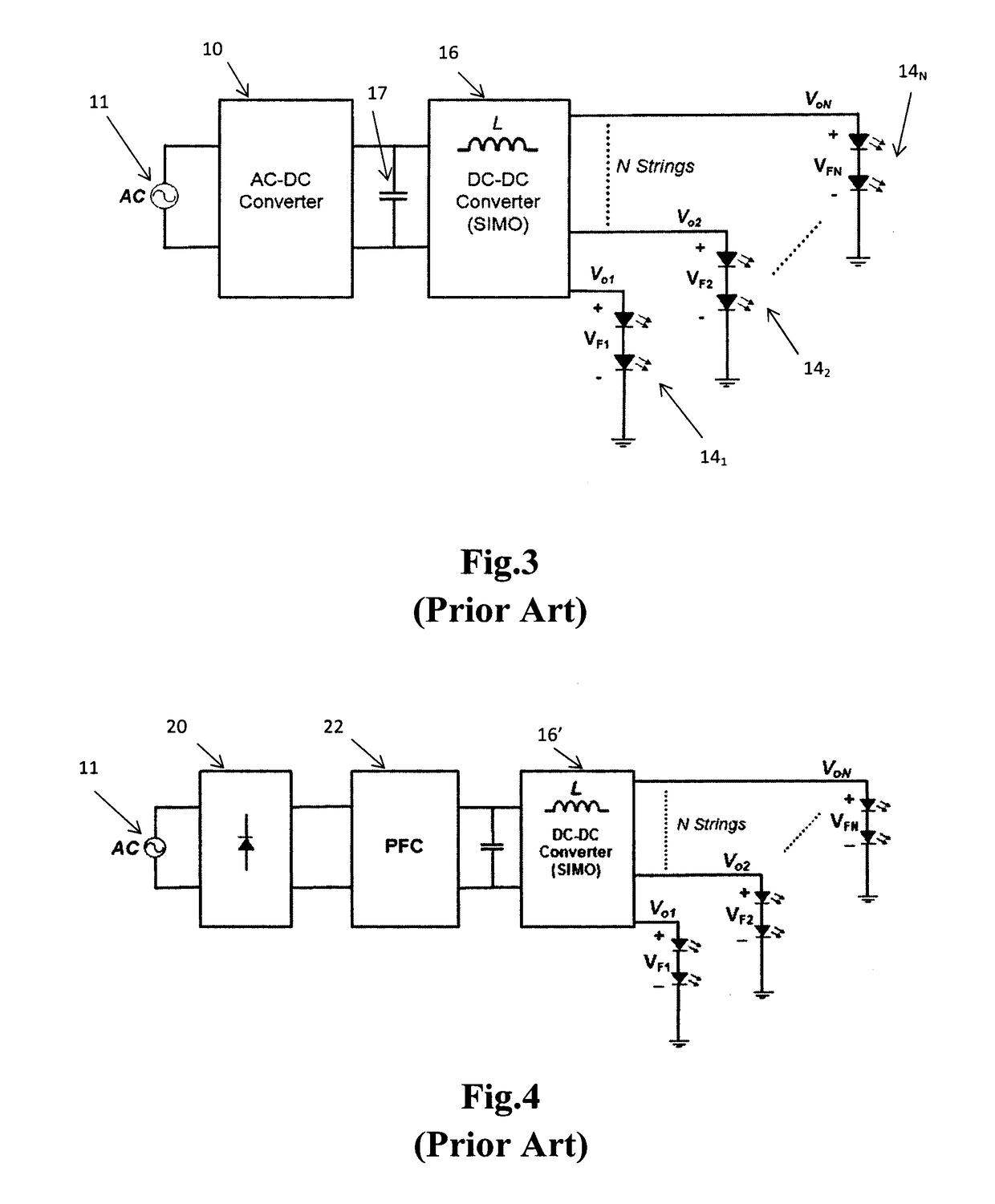
It is evident that the control logic for this two-stage system is quite complicated as it involves a front-end and back-end controller.
A major drawback for this particular AC-DC SIMO LED driver is that it does not support unequal currents across LED strings, i.e. so-called unbalanced loads.
In addition, the fact that it operates in a continuous conduction mode (CCM) and employs only a single energizing phase per switching cycle means that it suffers from serious cross-regulation among the LED strings.
A load transient in one LED channel will inevitably affect the DC operating point in other unchanged LED channels.

Method used


Image

  • Ac-dc single-inductor multiple-output LED drivers
  • Ac-dc single-inductor multiple-output LED drivers
  • Ac-dc single-inductor multiple-output LED drivers

Examples


Embodiment Construction

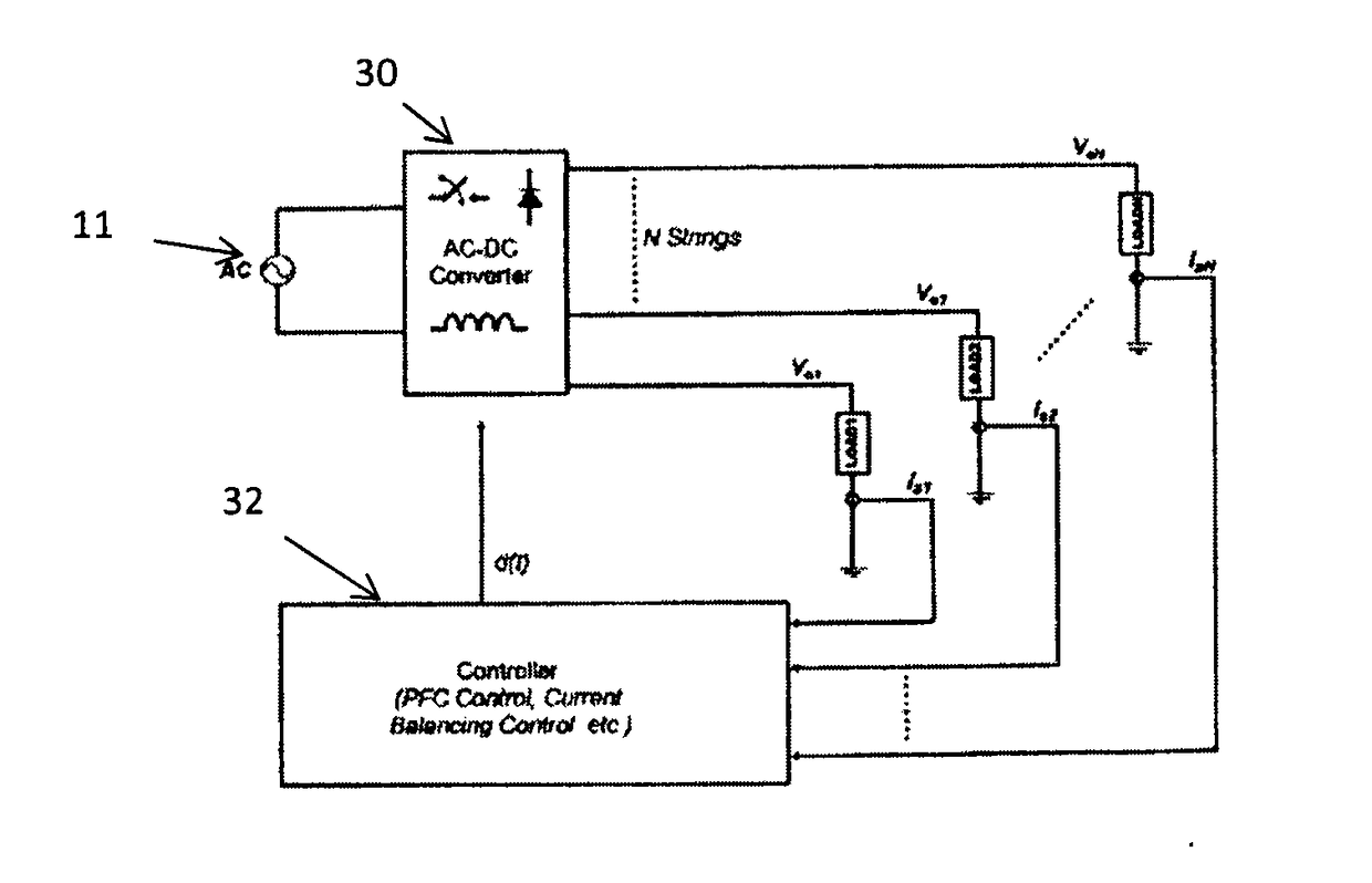
[0041]FIG. 5 shows a simplified functional block diagram of the LED driver according to the present invention. As shown, the AC mains input voltage 11 is rectified by a diode bridge 20 to create a DC voltage. For the sake of clarity, “mains” electricity is the general-purpose alternating-current (AC) electric power supply. In the US, this electric power supply is referred to by several names including household power, household electricity, house current, power line, domestic power, wall power, line power, AC power, city power, street power, and grid power.

[0042]A small filter capacitor 17 is connected to the output of the diode bridge in order to smooth the output voltage ripple. The rectified voltage and current then enter the power stage of the DC-DC Converter 16. This may be, for example, a buck converter. A buck converter is a DC to DC converter as shown in FIG. 13 with a switching transistor 130 between its input and a so-called “flywheel circuit” that includes an inductor 132...


PUM


Abstract

A single-stage AC-DC single-inductor multiple-output (SIMO) LED driver uses a single inductor (L) to drive multiple independent LED strings (341-34n) with Power Factor Correction (PFC). The driver uses a diode bridge (20) to achieve initial AC to DC conversion. The output of the bridge (20) is provided to a buck converter whose output is shared with multiple LED strings by a time division multiplex circuit. Feedback is used to separately control the current supplied to each LED string by using a separate reference for each string and controlling the width of the current pulse provided to a string. Current balancing in every LED string can be achieved with the same voltage reference without the need for additional circuitry.

Description

FIELD OF THE INVENTION[0001]The present invention relates generally to a single-stage AC-DC single-inductor multiple-output (SIMO) power converter, which transforms a universal AC mains source into multiple DC output voltages, each of which can be individually connected to an LED string. More particularly, the present invention relates to a SIMO with Power Factor Correction (PFC) and independent control of output currents.BACKGROUND OF THE INVENTION[0002]The market for light emitting diodes (LEDs) has a high potential in the global general lighting market. Light management systems and color control of LED light, which can affect the mood of the end users, enabling a purpose-friendly ambience, will shape the market into a new sphere.[0003]There is currently a strong demand for color (RGB) and tunable white LED lamps with reduced costs and smaller form factor. Many companies are interested in producing and selling innovative and cost-effective solutions for driving multiple LED string...

Claims


Application Information

Patent Timeline
IPC IPC(8): H05B33/08H02M7/06H02M1/14H02M3/156H05B44/00H05B45/10H05B45/325H05B45/36H05B45/375
CPCH05B33/0827H02M7/06H05B33/0818H05B33/0866H02M1/14H02M3/156H02M1/42H02M3/158H05B45/46H05B45/375Y02B20/30H02M1/009H05B45/24
Inventor GUO, YUELEE, TING LEUNG ALBERTLI, SINANTAN, SIEW CHONGLEE, CHI KWANHUI, SHU YUEN
Owner VERSITECH LTD
Learn More