Radioluminescent Phototherapy Eye Device

a radiation-luminescent and eye-mounted technology, applied in the field of radiation-luminescent phototherapy eye-mounted devices, can solve the problems of not treating the underlying cause of the disease, the upper limit of the oxygen that can be delivered to the cells within the retina, and the inability to achieve the effects of preventing appreciable cone stimulation, preventing hypoxia, and facilitating treatmen

Active Publication Date: 2018-04-05
CALIFORNIA INST OF TECH
View PDF2 Cites 34 Cited by
  • Summary
  • Abstract
  • Description
  • Claims
  • Application Information

AI Technical Summary

Benefits of technology

[0008]Embodiments of the present disclosure are directed to a phototherapy eye device, which overcomes challenges of compliance and dosage to make ocular phototherapy more effective and appealing. In various embodiments, the eye device includes a number of radioluminescent light sources and an anchor. Each radioluminescent light source includes an interior chamber coated with phosphor material, such as zinc sulfide, and containing a radioisotope material, such as gaseous tritium. The volume, shape, phosphor material, and radioisot

Problems solved by technology

This puts an upper limit on the amount of oxygen that can be delivered to the cells within the retina.
The increase in rod metabolism during dark adaptation can lead to hypoxia within the retina as demand outstrips diffusional supply.
This can reduce the ingrowth of new blood vessels onto the retina which helps mitigate vision loss; however, it does not treat the underlying cause of the disease, hyp

Method used


Image

  • Radioluminescent Phototherapy Eye Device
  • Radioluminescent Phototherapy Eye Device
  • Radioluminescent Phototherapy Eye Device

Examples


Embodiment Construction

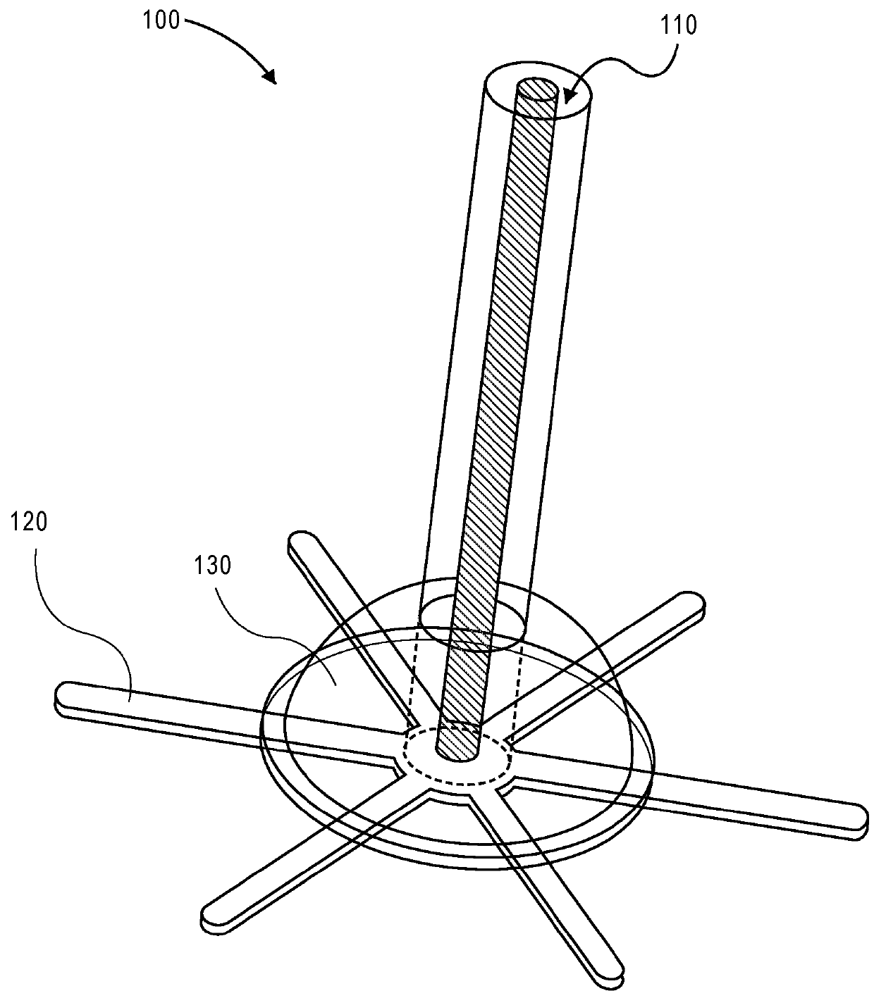
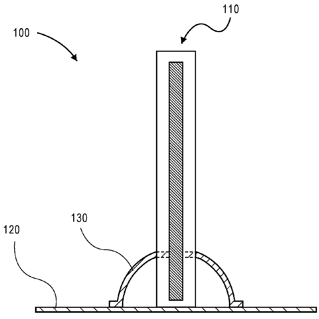
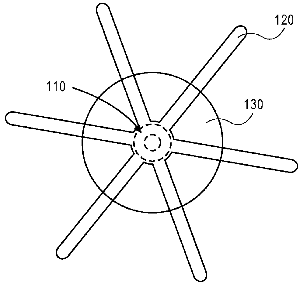
[0039]Embodiments of the present disclosure are directed to a phototherapy eye device, which overcomes challenges of compliance and dosage to make ocular phototherapy more effective and appealing. Generally, the phototherapy eye device includes a radioluminescent light source that emits light having, at peak emission, a wavelength between 400 nm and 600 nm (1.57×10⁻⁵ inch to 2.36×10⁻⁵ inch) and produces an irradiance on the retina of substantially 109 to 1011 photons / s / cm2. The irradiance at the surface of the radioluminescent light source is higher but decreases with the distance away from the source (by conservation of energy) since the surface area over which those photons are spread is increased. Ideally, the wavelength of the light should overlap with the maximum absorbance of rod cells / rhodopsin while being far from the maximal absorbance of blue or green cones, thereby minimizing the visual side effects of continuous phototherapy and maximizing the efficiency of the photother...


PUM


Abstract

Embodiments of the present disclosure are directed to a phototherapy eye device. In an example, the phototherapy eye device includes a number of radioluminescent light sources and an anchor. Each radioluminescent light source includes an interior chamber coated with phosphor material, such as zinc sulfide, and containing a radioisotope material, such as gaseous tritium. The volume, shape, phosphor material, and radioisotope material are selected for emission of light at a particular wavelength and delivering a particular irradiance on the retina (when implanted in an eyeball). The wavelength is in the range of 400 to 600 nm and the irradiance is substantially 109 to 1011 photons per second per cm2.

Description

CROSS-REFERENCES TO RELATED APPLICATIONS[0001]This application claims benefit of U.S. Provisional Application No. 62 / 403,569, filed Oct. 3, 2016, which is hereby incorporated in its entirety for all purposes.STATEMENT AS TO RIGHTS TO INVENTIONS MADE UNDER FEDERALLY SPONSORED RESEARCH AND DEVELOPMENT[0002]NOT APPLICABLEBACKGROUND OF THE INVENTION[0003]Many ophthalmological conditions, such as diabetic retinopathy, age related macular degeneration, retinopathy of prematurity, arise from aberrant angiogenesis, driven in part by expression of vascular endothelial growth factor (VEGF) in response to the oxygen deprivation of cells. The oxygen tension within the retina of the eye is of primary concern in these diseases and is a function of supply (oxygen diffusion from the choroid and retinal capillaries) and demand (primarily from photoreceptors and nerve cells). The retina is a multilayered structure composed of various photoreceptor and nerve cells sandwiched between the retinal and ch...

Claims


Application Information

Patent Timeline
IPC IPC(8): A61F2/16A61K9/00A61K51/12A61N5/04A61N5/06
CPCA61F2/1613A61K9/0051A61K51/1282A61N5/045A61N5/0622A61N5/1001A61F2002/1699A61N2005/0656A61K49/0015A61N5/0601A61N2005/0648A61N2005/0662A61L27/54A61L2300/44A61L2430/16A61F2/16G02C7/04G21H3/02A61F9/00
Inventor TAI, YU-CHONGCOOK, COLIN A
Owner CALIFORNIA INST OF TECH
Why Eureka
Try Eureka