
Drivetrain for a hybrid vehicle

a hybrid vehicle and drivetrain technology, applied in mechanical equipment, transportation and packaging, gearing, etc., can solve the problems of inability to braking by the drive unit, limited braking, and inability to do so, and achieve simple and compact construction, low drag torque, and simple operation.

Active Publication Date: 2018-04-26
BORGWARNER INC
View PDF2 Cites 2 Cited by
  • Summary
  • Abstract
  • Description
  • Claims
  • Application Information

AI Technical Summary

Benefits of technology

The present invention is about a new drivetrain for hybrid vehicles that has a simple and compact construction. It includes an electric machine and a double clutch device that has low torque drag and is easy to operate. The double clutch device can be arranged in parallel or axially staggered to reduce the installation space. The electric machine can be nested with the clutch arrangement or arranged axially staggered. The double clutch device and the electric machine form a module that can be easily connected and disconnected from the electric machine and the transmission. The invention allows for a simpler and more compact assembly and disassembly of the drivetrain.

Problems solved by technology

The known drivetrain has proven itself; however, since the freewheel is connected in the input side of the double clutch device and thus both before the first and the second clutch arrangement, a braking by the drive unit, the so-called engine braking, is not possible when the vehicle slows or rolls downhill.
Braking is also limited due to the energy recovery by the electric machine, both due to the battery size and also due to the charge state of the battery.

Method used


Image

  • Drivetrain for a hybrid vehicle
  • Drivetrain for a hybrid vehicle
  • Drivetrain for a hybrid vehicle

Examples


first embodiment

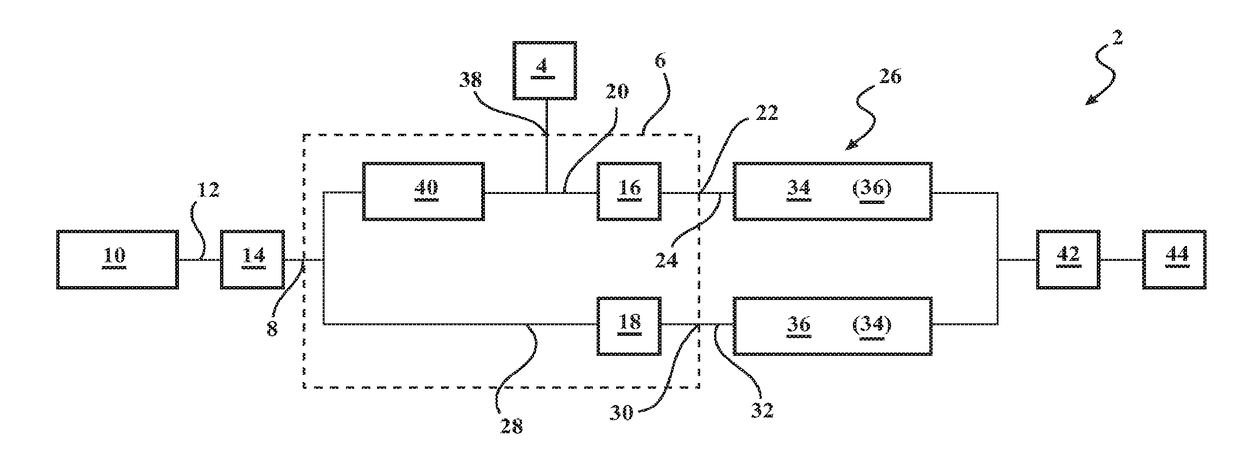
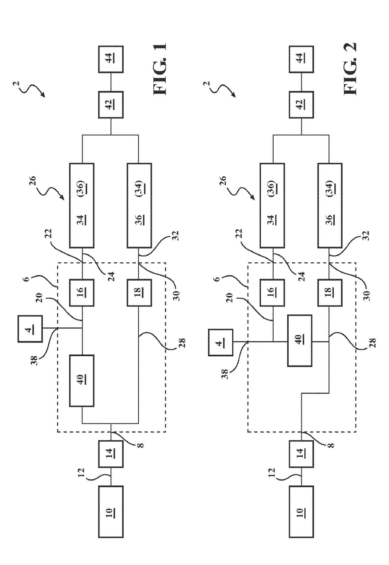
[0026]FIG. 1 shows a drivetrain 2 for a hybrid vehicle. Drivetrain 2 has an electric machine 4 which may be operated both as a generator and as an engine. In addition, drivetrain 2 has a double clutch device 6. Double clutch device 6 has an input side 8 which is assigned to a drive unit 10 in the form of an internal combustion engine. Stated more precisely, an output side 12 of drive unit 10 is in rotational driving connection with input side 8 of double clutch device 6, wherein the rotational driving connection is carried out in this case indirectly via torsional vibration damper 14 which is arranged between input side 8 of double clutch device 6 and output side 12 of drive unit 10.

[0027]Double clutch device 6 has a first clutch arrangement 16 and a second clutch arrangement 18 which are formed preferably as disk clutches, particularly preferred as wet-running disk clutches. First clutch arrangement 16 has a first clutch input side 20 and a first clutch output side 22, wherein firs...

second embodiment

[0032]FIG. 2 shows drivetrain 2 which corresponds substantially to drivetrain 2 of FIG. 1, so that subsequently only the differences will be introduced; identical reference numerals are used for identical or similar parts and the preceding description correspondingly applies in general.

[0033]As is clear from FIG. 2, first clutch input side 20 of first clutch arrangement 16 in the second embodiment is connected to second clutch input side 28 via a freewheel 40 so that first clutch input side 20 of first clutch arrangement 16, via freewheel 40, and second clutch input side 28 of second clutch arrangement 18 are, if necessary, in rotational driving connection with input side 8 of double clutch device 6, whereas second clutch input side 28 is furthermore in continuous rotational driving connection with input side 8 of double clutch device 6 without an intermediary acting freewheel 40, as this has already been previously explained. In general, the preceding embodiments correspondingly ap...

third embodiment

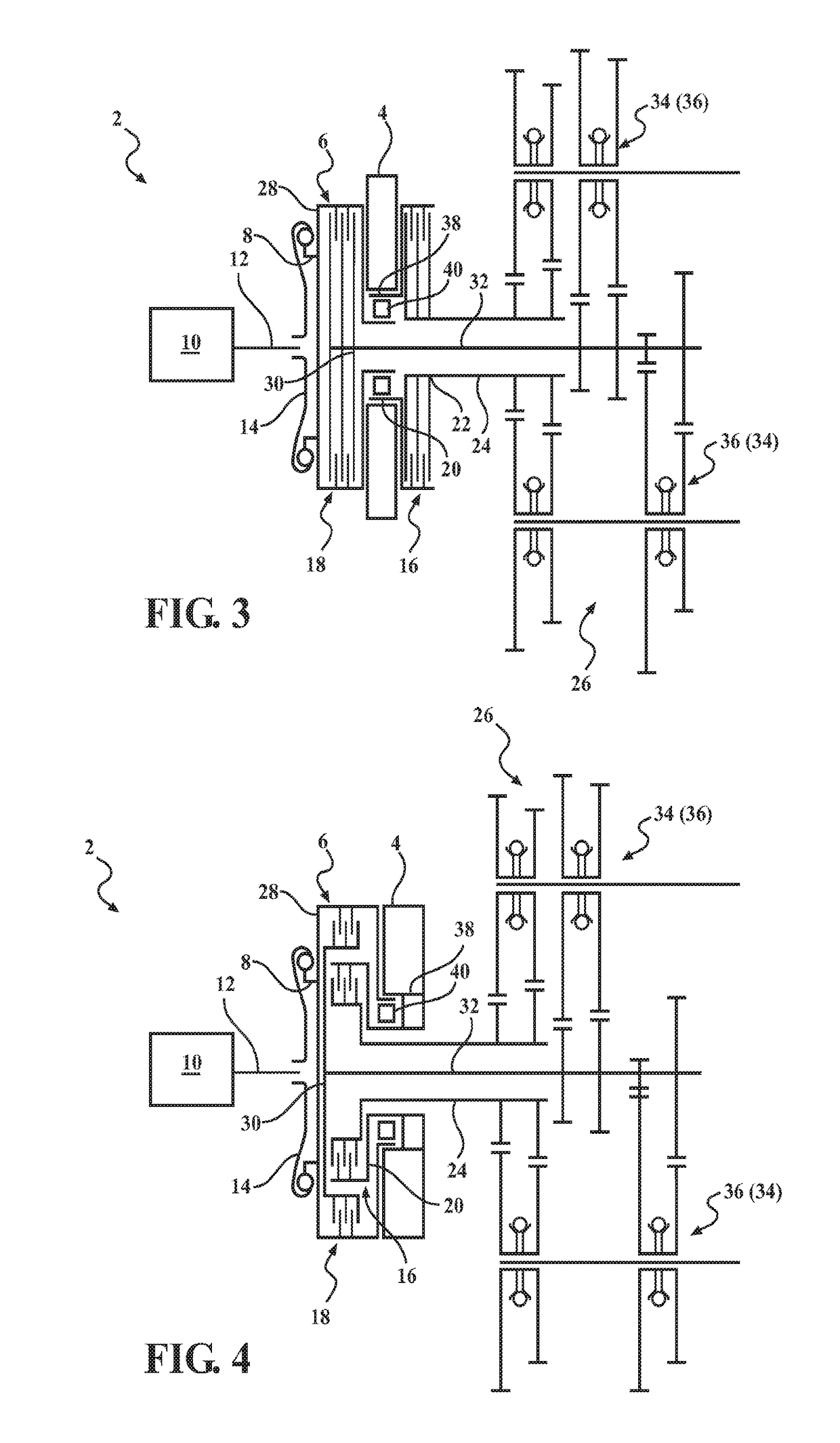
[0034]FIG. 3 shows drivetrain 2 which corresponds substantially to drivetrain 2 of FIG. 2, so that subsequently only the differences will be introduced; identical reference numerals are used for identical or similar parts and the preceding description correspondingly applies in general.

[0035]As is clear in FIG. 3, first and second clutch arrangements 16, 18 are arranged in parallel or axially staggered, wherein the two clutch arrangements 16, 18 of double clutch device 6—as already previously mentioned—are designed as disk clutches. It is also clear in FIG. 3 that electric machine 4 is arranged axially staggered with first and second clutch arrangements 16, 18, wherein electric machine 4 is arranged between first and second clutch arrangements 16, 18 in the axial direction. In general, the preceding embodiments correspondingly apply for the embodiment according to FIG. 3.


PUM


Abstract

A drivetrain for a hybrid vehicle comprising an electric machine and a double clutch device (which has an input side assigned to a drive unit, a first clutch arrangement assigned to a first transmission input shaft of a transmission for selective torque transmission between the drive unit and the first transmission input shaft, and a second clutch arrangement assigned to a second transmission input shaft of the transmission for selective torque transmission between the drive unit and the second transmission input shaft, wherein the first clutch arrangement has a first clutch input side which interacts with the electric machine, and the second clutch arrangement has a second clutch input side, wherein the first clutch input side of the first clutch arrangement is connected to the input side of the double clutch device via a freewheel or to the second clutch input side of the second clutch arrangement.

Description

CROSS REFERENCE TO RELATED APPLICATIONS[0001]This application is a National Phase of International Patent Application No. PCT / US2016 / 027026 filed on Apr. 12, 2016, which claims priority to and all the benefits of German Patent Application No. 102015004572.5 filed on Apr. 14, 2015 and German Patent Application No. 102016002908.0 filed on Mar. 10, 2016, both of which are hereby expressly incorporated herein by reference in their entirety.BACKGROUND OF THE INVENTION1. Field of the Invention[0002]The present invention relates to a drivetrain for a hybrid vehicle.2. Description of the Related Art[0003]A drivetrain for a hybrid vehicle is known from DE 10 2012 006 730 A1, wherein the drivetrain has an electric machine and a double clutch device. The double clutch device has an input side assigned to the drive unit or connectable to an output side of a drive unit, for example, an internal combustion engine. In addition, the double clutch device has a first clutch arrangement assigned to a ...

Claims


Application Information

Patent Timeline
Patent Type & Authority Applications(United States)
IPC IPC(8): B60K6/547B60K6/383F16H3/00B60K6/36
CPCB60K6/547B60K6/383F16H3/006B60K6/36B60K6/44B60Y2200/92B60Y2300/424Y10S903/913Y10S903/909Y10S903/919B60K6/38B60K6/48B60K2006/4825B60K6/40Y02T10/62
Inventor SCHNEIDER, FLORIANSAXENA, VIRENHAUCK, HANS JUERGENMOSER, ALEXANDERKOESTEL, ROLF
Owner BORGWARNER INC
Learn More